• ***AVOID MARKETPLACE SCAMS!!***

    Scammers are using compromised Prime member accounts to pose as a trusted seller in the marketplace. Before you enter into a deal with any seller, follow these tips to keep yourself safe. If you encounter one of these scammers, please report them immediately and we will lock their account.

    Caveat Emptor!

LED Rear Tail Lamps!?!?!?

That had crossed my mind Dutch' - without being able to access the actual indicator circuit it possibly would need that additional relay. That would guarantee it would work as intended if it does need to start in an "off" condition.

I may just try shorting that wire to ground to simulate & see what happens to see if the relay is really necessary.

On your second point, it's just as simple as finding a relay that will work with the appropriate current spec - the original may even work, even with a lower current. (SSR doesn't work like conventional electromagnetic relay)
 
Kinan said:
I did this a few years ago with some aftermarket LED bulbs. Basically, I measured the current draw of the existing bulbs, then the current of the new LED bulbs and noted the difference.
Then I calculated the remaining resistance that needed to be added the to the circuit to bring the current draw to where it was with the old bulbs.

Depending on what kind of current the LED bulbs draw will determine the new resistance.
As far as the power rating, it worked out to something around 12 watts if I remember correctly. I installed 25 watt 10 Ohm resistors and haven't had any problems in 2 years here in warm southern California.

So what you need to do is start making kits so a person like me who knows very little about electronics, can plug and play. Obviously the mark is set at $1600...I imagine if you made a kit for say, $300 you'd sell a TON. (I can't imagine the actual parts involved would top $200...the prices of LEDS are becoming very inexpensive.)
 
I don't know as much as the last two post but I do know something about taking these lights apart, I have done 5 sets now.

1.Grounding can fool the failure indicator and it also lets the cruise control work.
2. You cannot go through the back of the light and have any studs left to re-mount the lights.
3. I used resistors to slow the blinkers. They do not build heat in the blinkers and there is not a plug and play flasher that will work.
4.The lights need to be in good condition or you have a high risk of "running" an existing stress or heat fracture across the lens.
5. I will be building these in a round version and a square version and they will cost between $700 and $900 depending on the amount of letter removal desired. An acceptable core is needed or it is a no go. My LEDs will not fill the entire housing with lights like Clear Corners, but they will be half the price and Plug and Play.

I will post in the vender section with pictures and details as soon as I can.

Joe
 
Good on you Joe - let me look into a plug n play relay for the flashers for you.
I might be able to mod something up for you.

Special "considerations" on a LED conversion appreciated! <!--StartFragment -->
pain.gif


On the brake light sensor - are you confirming my previous post that you simply ground the output & no additional relay is required?
 
D'Ecosse said:
On the brake light sensor - are you confirming my previous post that you simply ground the output & no additional relay is required?

Seems like he tried and succeeded (as i read his post). I wonder though why the brakepedal trick didn't work.
Well, it doesn't matter now, the problem is solved the easy way.
 
jdnsx said:
4.The lights need to be in good condition or you have a high risk of "running" an existing stress or heat fracture across the lens.
5. I will be building these in a round version and a square version and they will cost between $700 and $900 depending on the amount of letter removal desired. An acceptable core is needed or it is a no go. My LEDs will not fill the entire housing with lights like Clear Corners, but they will be half the price and Plug and Play.

I will post in the vender section with pictures and details as soon as I can.

Joe

The round ones look cool! I think you'll have quite a few clients. Definitely on my list.
 
jdnsx said:
Yes. See this thread.
Somehow missed that first time around.
From your above referenced thread Joe, from Hugh:

Hugh said:
blfs_mod.jpg


Well it almost worked. I had to do one more thing to make the idiot light go away for good. I cut the White/Green wire to the right of the blue plastic tap connector so it is no longer connected to the sensor. It is simply grounded now.

From previous post Hugh had stated the white/green wire is actually connected to the orange/white from the schematic posted above - in the pic he shows the white/green wire connected to chassis ground via a wire-tap.

From same thread post # 60 by MarkB you can indeed see the output form detector is white/green connecting on to orange/white wire.

attachment.php


I would have to question what difference cutting the wire to disconnect the sensor circuit would make - ground would still be permanent on that line regardless of connection to the detector or not (which only supplies ground via the relay contacts anyway)
 
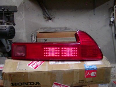
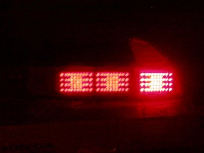
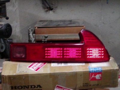
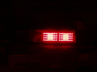
Is it hip to be square? The photo quality is poor, lights are hard to capture.
 

Attachments

  • SQLT8.JPG
    SQLT8.JPG
    68.3 KB · Views: 843
  • SQLT3.JPG
    SQLT3.JPG
    41.5 KB · Views: 840
  • SQLT.JPG
    SQLT.JPG
    61.6 KB · Views: 837
  • SQLT5.JPG
    SQLT5.JPG
    31.6 KB · Views: 1,703
SNDSOUL said:
I like the squares!!, but whats with the squares in the middle of the leds?

Thats just the way the LED boards come. My wife likes the square in the middle of the square because it looks like a modern rendition of the NSX lenses.
 
Joe, we are all obsessed that's why NSXPrime exists!!!! :smile: :smile:
 
This is going to be my fall project - I'm thinking of full bar however with a custom hand-built array of LED's as opposed to individual light clusters. Maybe even convert the centre section to a "lit" section also instead of just being a dummy.

I'm excited about it already.

Currently I'm not looking to market these in competition to Joe or Clearcorners incidentally, but just for personal satisfaction of doing the project. There's just such an incredible amount of work in doing something like this - although it seems expensive to some people at first reaction I can see why these prices are justified. Even with Joe's method of utilizing existing clusters & retrofitting them into the OEM lamp shells takes a lot of labour as well as the outlay for the parts. Then there is the potential risk of damaging a light shell - there goes the "profit"!
 
mackash said:
Joe
Have you done the 02 tail lights if so what did you use in the turn signal?

I have not done any yet. The round LED is almost the exact size as the round amber lens so it should work nicely. I also have an oval that might even be better but I have to buy a set of 2002 lights to experiment with.

Joe
 
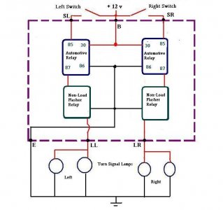
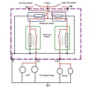
OK - here's how to make the flasher module work with LED's to overcome the rapid blink rate (since the OEM flasher will think a bulb is out due to reduced current):

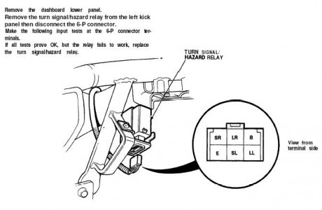
There is no "plug n play" replacement, but a functional unit can be easily fabricated & wired up to the appropriate connections on the relay connector plug under the dash. You could even use the original relay base as a plug if desired which would avoid having to tap into your wiring.

You can select from a couple of basic elements from a couple of sources

http://www.superbrightleds.com/1157.htm (new item - check about half-way down page)

or

http://www.usaled.com/store/item/opy8/EL98_Audible_LED_Flasher/EL98N_LED_BULB_FLASHER_8-_14_5_VDC_NON_BEEPER.html

You will need two of (either of) these electronic flasher relays & two regular automotive relays.

Here are the wiring diagrams to connect them up:


.
 

Attachments

  • flasher_relay_2.JPG
    flasher_relay_2.JPG
    52.3 KB · Views: 403
  • flasher_relay.JPG
    flasher_relay.JPG
    61.3 KB · Views: 408
Last edited:
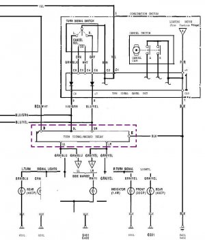
Here's the original circuit and the relay location under dash -

.
 

Attachments

  • flashrelayloc.JPG
    flashrelayloc.JPG
    38.2 KB · Views: 402
  • flashrelay.JPG
    flashrelay.JPG
    60.2 KB · Views: 332
Last edited:
jdnsx

hope you dont mind.. I posted the comparison of the round and square installation.. They booth look good.

My take.
Round. - a more custom look.
Square - modern OEM look.

attachment.php


6753Sq_installed_3.jpg


BTW have you seen www.Whelen.com emergency vehicle grade LED lightheads.. expensive tho.
 
Last edited:
Instead of simple straight lines take three elements per side and form the literals we like most: N-S-X as parking light and quadratic as brake light? :)
Just a little input.
 
Back
Top