• ***AVOID MARKETPLACE SCAMS!!***

    Scammers are using compromised Prime member accounts to pose as a trusted seller in the marketplace. Before you enter into a deal with any seller, follow these tips to keep yourself safe. If you encounter one of these scammers, please report them immediately and we will lock their account.

    Caveat Emptor!

LED Rear Tail Lamps!?!?!?

Joined
6 January 2004
Messages
127
Location
Pasadena, CA
I've upgraded to '02/ margahills the body on my x. However, I feel the tail lamps (even the 02) seem very antiquated..80s supercar-ish. Does anyone know of any aftermarket rear tail lamp assemblies? How expensive will it be to manufacture an LED tail lamp...do you think there is a market for it?

Thank you,

speedyizzy
 
If someone was to make one for around $500 I would buy one but for $1500 ill pass.
 
I like the clearcorners execution a lot, but have not purchased because of A) cost B) the brake fault light I am expecting C)the splicing of wires and D) I'd rather the turn LEDs be amber. Picky I know, but it seems like it should be possible to design around without too much hassle.

some broken tail light bulbs with wires soldered onto the voltage leads, and filled with rubber/epoxy should be a decent way to connect to the OEM harness. With a breadboard it should be easy (but tedious) to solder all these little LEDs in a criss-cross pattern so that no lights looks like this
- - - - - - - -
- - - - - - - -
- - - - - - - -
Headlights looks like this
- X - X - X - X
X - X - X - X -
- X - X - X - X
Full Brakes Looks like this
X X X X X X X X
X X X X X X X X
X X X X X X X X

When paired up with resistors of the proper values, it SEEMS like the brake fault could be eliminated. Some sandpaper, plastic polish and a candy coating of paint and I could have my ideal tail lights. JDM dark plastic lenses, with an 02+ acura logo in the middle, with Red and Orange LEDs, and all the DOT text polished out.

As you can tell, I have been thinking about this for quite a while. I was hoping that my laziness & frugaillity would combine to push this out of my mind but it has not happened yet. Maybe I should start looking for a spare set of lenses to play with.
 
White94 said:
I like the clearcorners execution a lot, but have not purchased because of A) cost B) the brake fault light I am expecting C)the splicing of wires and D) I'd rather the turn LEDs be amber. Picky I know, but it seems like it should be possible to design around without too much hassle.

some broken tail light bulbs with wires soldered onto the voltage leads, and filled with rubber/epoxy should be a decent way to connect to the OEM harness. With a breadboard it should be easy (but tedious) to solder all these little LEDs in a criss-cross pattern so that no lights looks like this
- - - - - - - -
- - - - - - - -
- - - - - - - -
Headlights looks like this
- X - X - X - X
X - X - X - X -
- X - X - X - X
Full Brakes Looks like this
X X X X X X X X
X X X X X X X X
X X X X X X X X

When paired up with resistors of the proper values, it SEEMS like the brake fault could be eliminated. Some sandpaper, plastic polish and a candy coating of paint and I could have my ideal tail lights. JDM dark plastic lenses, with an 02+ acura logo in the middle, with Red and Orange LEDs, and all the DOT text polished out.

As you can tell, I have been thinking about this for quite a while. I was hoping that my laziness & frugaillity would combine to push this out of my mind but it has not happened yet. Maybe I should start looking for a spare set of lenses to play with.

I looked into it, and the cost clearcorners is making, is mainly from taking the light apart, and the risk involved doing so.
Now, you might not wanna do that, but your stuck with the diffuser inbetween the housing and the red lens, which offcourse can be left alone, but will have negative effect on the appareance.
Leaving the light intact is an option, but you need to get that aray of LEDS into the housing, which means, cutting the rear off.

Choosing the color of the LEDS is no problem, the fault light can be sorted with a simple relay, or while your working with a PCB, a small transistor and some parts.
If you want it to be functional, its a completely different story. Can be done though.
Using a resistor to 'fake' the bulb is a risky option imho, your going to disapate quite some heat in a resistor, which wil get hot hot hot. A simple relay would be a much better idea i suppose.
 
I already have a spare set sitting here, I'm just waiting for someone to take on the job.

I took apart my center tail piece and made quite a few mini cracks inside, that's why I'm not touching the taillights.

I bet there must be some solvent that we can use to soften the glue instead of hot water.... anyone? Bueller??

Henry.
 
DutchBlackNsx said:
I looked into it, and the cost clearcorners is making, is mainly from taking the light apart, and the risk involved doing so.
Agreed, it is definitely a fair price for the time and risk involved. However, I'd rather try it myself so I can customize it a little and because I think it would be an interesting project. :smile:

DutchBlackNsx said:
Now, you might not wanna do that, but your stuck with the diffuser inbetween the housing and the red lens, which offcourse can be left alone, but will have negative effect on the appareance. Leaving the light intact is an option, but you need to get that aray of LEDS into the housing, which means, cutting the rear off.
I am with you, if I ever do this I am going to pull the lenses apart, remove diffuser, polish/paint lenses, install PCB, & reseal.

DutchBlackNsx said:
Choosing the color of the LEDS is no problem, the fault light can be sorted with a simple relay, or while your working with a PCB, a small transistor and some parts. If you want it to be functional, its a completely different story. Can be done though.Using a resistor to 'fake' the bulb is a risky option imho, your going to disapate quite some heat in a resistor, which wil get hot hot hot. A simple relay would be a much better idea i suppose.
Good idea, I will have to check into that. My knowledge does not extend much beyond basic circuits, so I have plenty of stuff to research if i ever get to it. Thanks for the pointer!

Basic wiring seems like you could run each brake/headlight/turn 12V loop though through into a load to get the resistance you need not to trip the fault sensor, and then split the 12V source into equal # (and resistance) parallel arrays to get the input voltage needed for the LEDs. I was thinking 9 arrays per side (3 Red brake, 3 Red headlight, 3 Amber turn) would probably work to give ~4V for a group of LEDs in parallel, but really have not gotten much past the daydreaming stage at this point.

If my ramblings are useful to anyone, feel free to steal the idea. If not, feel free to ignore. :smile:
 
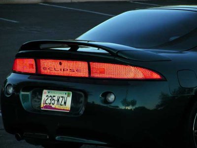
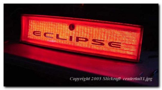
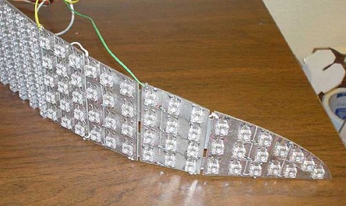
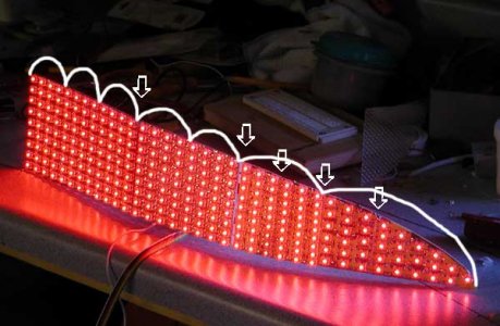
LED Section -> look for a thread titled 98 Eclipse Tail Light Conversion Project

Summary: Some guy converts his Eclipse to a 8xx LED array with custom power supplies and circuitry. Looks VERY good.


See if any of the attached interest you:
 

Attachments

  • tailtrial1.jpg
    tailtrial1.jpg
    22.8 KB · Views: 4,087
  • centertail1.jpg
    centertail1.jpg
    32.4 KB · Views: 1,138
  • cornerboard2.jpg
    cornerboard2.jpg
    38.3 KB · Views: 4,030
  • boardtaper.jpg
    boardtaper.jpg
    34 KB · Views: 1,171
nsxhk said:
I already have a spare set sitting here, I'm just waiting for someone to take on the job.

I took apart my center tail piece and made quite a few mini cracks inside, that's why I'm not touching the taillights.

I bet there must be some solvent that we can use to soften the glue instead of hot water.... anyone? Bueller??

Henry.

How about a Dremel tool with a rotary cut off wheel?
 
No way. It has to reseal, which means no cosmetic damage. Unfortunately, the only solvents that I know of will also etch the plastic and ruin it's transparency.
 
Clearcorner's are now $1,675.00 for 91-01, and $1,785.00 for 92-xx.

I've long waited for LED taillamp and decided to go with Clearcornes, price is high but haven't found another option professionally done at a lower price.

I e-mailed them and Michael reply next day. I asked for the option to add rear fog lamps and Michael is very open to do any mods. He suggested placing a dual array (white and red) of leds in the reverse lamp. Fog lamps will be turned on and off by a JDM switch offered by SoS.

I believe Clearcorners is the way to go.
 
Clear corners is very expensive, but they do a great job....

I would have to imagine there is a cheaper alternative....heck for that price, I'd rather buy the LEDs and have a go at it myself.
 
DrVolkl said:
Clear corners is very expensive, but they do a great job....

I would have to imagine there is a cheaper alternative....heck for that price, I'd rather buy the LEDs and have a go at it myself.

I think clearcorners is using a more rudimentary design. With the design that this guy used, you get more even illumination (wide angle LEDs) and you also get the ability to have any brightness setting. It uses variable, imperceptable pulse settings for each array so brake and running lights can run off the same LED with varying intesity. IMO, VERY cool technology. Including the power supplies, PCB, LEDs, resistors, spare tails, etc this guy said he spent $800. With 80-100 hour labor including design, I am NOT disputing that it is worth every cent for Clearcorners, but it sure does seem like a nice way to tinker and get exactly what you want for less money and more labor.

Plus, once the PCBs are made, arrays laid out, controllers and PS are designed this should be something that could be batched produced for equivalent or less pricing.
 
White94 said:
Good idea, I will have to check into that. My knowledge does not extend much beyond basic circuits, so I have plenty of stuff to research if i ever get to it. Thanks for the pointer!

Basic wiring seems like you could run each brake/headlight/turn 12V loop though through into a load to get the resistance you need not to trip the fault sensor, and then split the 12V source into equal # (and resistance) parallel arrays to get the input voltage needed for the LEDs. I was thinking 9 arrays per side (3 Red brake, 3 Red headlight, 3 Amber turn) would probably work to give ~4V for a group of LEDs in parallel, but really have not gotten much past the daydreaming stage at this point.

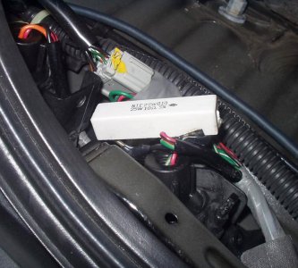
I did this a few years ago with some aftermarket LED bulbs. Basically, I measured the current draw of the existing bulbs, then the current of the new LED bulbs and noted the difference.
Then I calculated the remaining resistance that needed to be added the to the circuit to bring the current draw to where it was with the old bulbs.

Depending on what kind of current the LED bulbs draw will determine the new resistance.
As far as the power rating, it worked out to something around 12 watts if I remember correctly. I installed 25 watt 10 Ohm resistors and haven't had any problems in 2 years here in warm southern California.
 

Attachments

  • P1010329.2.jpg
    P1010329.2.jpg
    91.8 KB · Views: 1,127
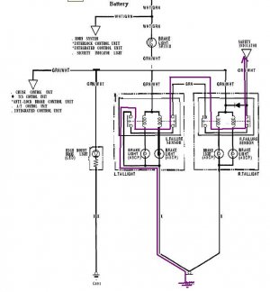
See the NSX brake light & detector circuit below.

How it works is, when each of the 4 lamp filaments conducts current then current also flows through each of the associated relay coils for that light. That current then energizes each of the relays & completes in series (daisy-chain) the circuit to ground for the safety indicator input.
(Follow the purple line for the completion of the circuit from safety indicator input to ground)

If any of the lamps is "open", then the associated relay will have no current through it's coil & that contact will remain "open", breaking chain to ground.
Notice there is no detector for the high-mount LED brake light.

The relays must be a relatively low voltage operated "coil" - although shown as a typical electromagnetic relay in the schematic, I suspect they are actually solid-state (electronic) relays. You would still desire close to 12 Volts on the brake lamps bulbs, so only dropping at most 1-2 volts across the coils max. Regardless however if the current is disproportionately too low for the leds compared to original lamps, the relay won't energize (depends on the relay's specifications).

The simple solution to eliminate the fail light from illuminating is simply to short the input of the safety indicator to chassis ground. If you still want to be able to detect failure in the new LED panels, it gets more complicated but quite do-able, simplest by just selecting a suitable SSR which will operate in the specified current range of the LED's
However I would suggest that the reason for the detector in the first place is because of the limited lifetime of incandescent bulbs - no such problem with LEDs.

My recommendation would be to simply tie the input signal to the safety indicator to ground & forget about the leds failing. This is certainly no different result (yet much simpler) than installing a resistor to make the OEM relay think there is a light bulb there! (i.e. if the LED is "out" the resistor will still complete the circuit anyway so isn't actually providing any detection for failure!)
 

Attachments

  • brakelight.JPG
    brakelight.JPG
    50.9 KB · Views: 1,485
D'Ecosse said:
See the NSX brake light & detector circuit below.

How it works is................. actually providing any detection for failure!

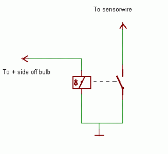
I was under the impression that the indicator circuit needed at least a 1 and a 0 to go off, incase there is a fault in the circuit.
I tried in my car, turned the key in 'on' position while having my foot on the brake pedal, indicator commes on, doesn't go off, pulse the circuit, and it goes off.

Though being a nOOb solution with a relais (prefferably high resistance 12VDC), i suppose this should do it.
Offcourse a true working transistorversion should be easy to build as well, actualy, you could fit it on the LED PCB, a devided voltage should be readily availble since those LEDS need a resistor anyway.
 

Attachments

  • relay.GIF
    relay.GIF
    2.6 KB · Views: 992
Back
Top