I was wrong, those numbers are off the dyno chart. The engine log has me at 11.7-12 all the way to 8500 RPM!
Good to hear, that is where you should be.
I was wrong, those numbers are off the dyno chart. The engine log has me at 11.7-12 all the way to 8500 RPM!
 )
)Sorry for the dumb question, but this is an air/water intercooler? I am a little confused. Are you running a vented hood for this?
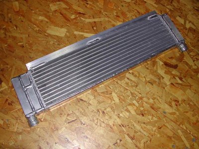
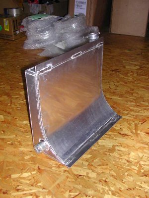
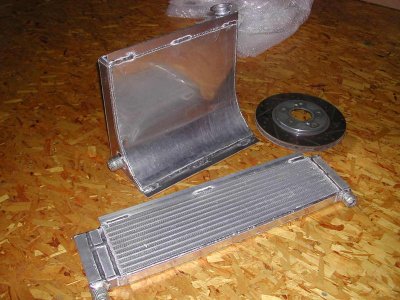
...the IC heat exchanger finally got here, and the custom tank...the tank sits where the spare tire used to be and is shaped to help push the air out of my hood. There is a flange on the top edge to bolt a deflector on to help seal against the bottom of the hood.
(note brake rotor for scale
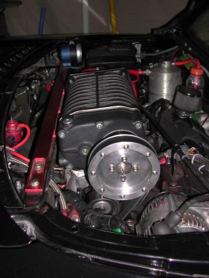
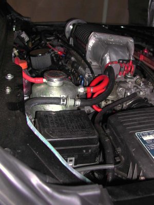
Nice work. Glad to see you have your motor installed I was wondering how tight it would be with the extra tensioner. My set up has two metal lines that I need to re-route I thing smog lines. The tank looks awesome.
Ken can you and Dave tell us how your setups differ? looks like you guys are using the same blower... right?
Ken, it would not fit with out the idler. The belt would run through the motor mount. The double bearing idler I am making will have flanges on it, to help the alignment of the belt.
Are you still using the 2 idler pulleys on the CT plate? I am not sure what the upside to the second 'grooved' pulley is? The smooth pulley increases wrap on the crank pulley, I am not clear if I need the second 'grooved' now I have the idlers pulley by the blower. I can shorten the belt quite a bit and it will be easier to thread the belt, not needing to do that extra loop...hmmm
Yes I still have all the Comptech pulley locations. I just increased the size from 5 grooves to 8 grooves. My top pulley is only about 3" in diameter and as I rev it up you can see it trying to lift up off the pulley. I plan on having a new one made soon and it will have much taller walls. I also have an aluminum plate that I purchased from Whipple that is sleeved to go over the blower snout and clamp down. That will hold my new idler. I just started looking at it last night so maybe over the weekend I will get a chance to work on it.
I like you idea about flanges on the idler. If you put them on all the pulleys we only have slippage. That I could live with.
Are you guys using tools like a flowbench to measure/test/equalize the flow to each cylinder thru the intake systems that you are fabricating?
bja
I bolted flanges on my blower pulley, that's why there are all those button head screws on the pulley! I used some 1/8" plate and cut out big washers, drilled/tapped the pulley and drilled the washers. Bolted it all together spun it on the lathe to make everything round again.
This was all about being lazy but it worked fine!
Bearings should be in tomorrow for the idler, I will post pics when it's back on.
Joe Downs had mentioned Whipple recommended against clamping on the OD of the snout for fear of loading the bearings as they expand from heat. I chose to make all my mounts off the CT plate to avoid that issue.
I just figured it out!!!!!

You put the motor in upside down AGAIN
No, sideways!
Duh:tongue:
 it will be cheaper and kick all our butts.
Good news I took the car out for a test ride yesterday with out building a new pulley tensioner plate and had no or very little slippage. The belt looks good so far. I need to get a tunner on board now.Hey guys,
I get a tear in my eye when I look at these two setups and realize how far we have come.:wink:
One of the things we have not talked about on Ken's car is how hard is it to turn the larger 2.3L input shaft with the 3 inch pulley. I am turning the 1.6L Whipple with a 2.9 inch pulley and have some belt lift if the tension is not right. The amount of torque and belt friction needed to turn the larger lobes of the 2.3 Whipple is going to be significantly higher.
The good news is the belt lift shows itself mostly when you rev the motor out of gear. The RPMs come up so fast that the belt can't push/pull the pulley fast enough and you get some lift. This does not happen in gear because the RPM increase, although fast, is slower and smoother.
Joe
I just figured it out!!!! The Comptech Supercharger kit tensions the wrong side of the belt! This set up has a spring loaded tensioner on the tensioned/pulling side of the belt. As the motor RPM increases, if the resistance to turning of the blower pulley is higher than the spring tension of the tensioner, the tensioner compresses and loosens the belt!
I have a Whipple set up from a Chevy I scavenged my blower off of, and it tensions the slack side of the belt, going from the crank up to the blower.
Check this out:
http://www.pfaffengines.com/850sc.shtml
Straight line from the blower pulley to the crank pulley, tensioner on the slack side!
Resurrecting a very old post, but this thing is finally running OK! I made questionable choice and put chrome rings in the motor when I put new pistons in it last fall, 4500 miles later they are seating! SO, now I can get some tuning done...
440.3 RWHP, 321 ft/lb. torque at 10.5 lb. of boost! Not bad for a 3.0L:biggrin:
Will post dyno graph tonight.
Still a little conservative with the A/F so there is more in it, 11.8 falling to 10.8 at 8000 RPM. Torque is pretty flat from 5K to 7K, falls off a bit above there so I am having a little belt slipping, which I am OK considering where I have been and how long this has taken. Current pulley should top out at 14 PSI, at least on paper, it holds flat from 6K up. The other cause would be a boost leak, so I will hunt around a bit. More soon:tongue: