intercooled 2.3 L supercharger/Comptech donor manifold

Joined
8 November 2003
Messages
2,412
Location
Portland OR
A while ago I posted pics of me cutting up one of the original Comptech hand built manifolds. I have been slowly putting it back together after I cut it to pieces...

First thread:

http://www.nsxprime.com/forums/showthread.php?p=825146#post825146

First I made some tanks...

Then I welded the tanks onto a 11x6x1.25" core...

Pressure test at 35 PSI overnight, found one leak, welded it up, re-test...it holds!...

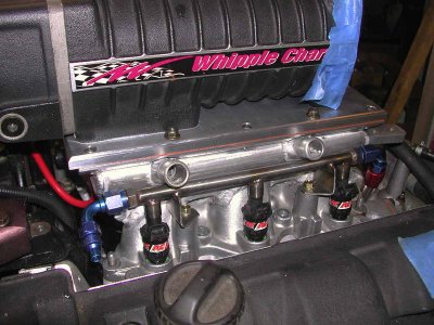
fit it onto the manifold...
 
Last edited:
Then it's time to weld the intercooler onto the manifold...

Clamp it so it stays flat...

Weld...

Weld...

And weld some more, finally finished!
 
Last edited:
Next, make a top flange, and you guessed it, weld some more...I figure I have about 20 feet of weld bead in this project so far, this is such great practice!

Deck the top of the flange(kept it with in .025" during welding!), drill and tap some holes to bolt on an adapter plate...

Deck the bottom where it bolts to the heads, also was less than .025" out post weld!

Finished manifold ready for the plate and mounting on the motor!
 
Last edited:
Adapter plate...

There is not a drive which is less than 3" long for the Whipple charger available, I need just under 2" so it's back to the lathe and mill to build a drive. Engineers at Whipple warned me I would break bolts off with a pulley 2" long, so I decided to make a drive which grabs on the face and the sides of the blower snout. This also allows me to adjust the run out at the pulley end. The blower snout where the pulley mounts has .001" of run out from the factory, and I am afraid it's going to make for problems down the road, so I was able to load my drive with the 4 set screws to get the run out to less than .0005" at the end where my new pulley will mount. I have also made the drive so the pulley will be a concentric fit onto the OD of the drive, so only shear loads will be taken by the bolts securing the pulley, should make the pulleys last for ever and keep the whole system from coming loose.

Here are shots of the whole mess bolted on top of the motor, fuel rails in place, and as you can see it's all tight but it fits! In the last shot you can see the throttle cable mount tab on the right side of the picture, just above the fuel rail. The top of that tab is the height of the 'stock' Comptech manifold. This is a good visual for how much height the intercooler core added.

More soon, final drive today and then the intake from the throttle body to the blower...
 

Attachments

  • manifold, fuel rails front side.jpg
    manifold, fuel rails front side.jpg
    92.2 KB · Views: 550
Last edited:
Here is the pump I am using:
EWP110: With a max. flow rate of 110 litres/min

http://www.daviescraig.com.au/main/display.asp?pid=47

I am limited to the size of core I want to run because I don't want to increase the height of the blower. The way I have chosen to increase the capacity to draw heat out of the compressed air is to flow as much water as possible through the core. I have chosen an overkill pump for that reason, plus I am using 2 3/4" inputs and outputs on the core, manifolded into 1" ID rigid lines to get the coolant to the front of the car. All are in the hope of getting the most volume through the core. These will be coupled with a 24x6x1.25" double pass heat exchanger hanging in front of my custom radiator.

More pics as I get parts finished.
 
OUCH, shit ain't funny man...

I used to drive it, and I will again!:rolleyes:
 
Weld...

Weld...

And weld some more.......

Sing the whole song you had going on in your head :biggrin: I love welding Al but you are truly NUTS :eek:

Anyone, (I would HOPE) can see the HUNDREDS of HOURS (if not the 1K hour mark) into this little project................that's just crazy and must be for the LOVE of something.

So, I'll be the first..........whens the GROUP BUY :tongue:? NOW if your hourly RATE is 5 CENTS an HOUR.............it would be.......$$$???/ :redface: :rolleyes: :wink:

Looks great man. Can't wait to see that long FLAT torque line on the dyno.
 
Looks great man. Can't wait to see that long FLAT torque line on the dyno.

Thanks, can't wait to see ANY torque curve on a dyno...:redface:

Been a loooooooonnnnnggggggg time....
 
Dave, I may be sending you more money once this becomes available to purchase.... :rolleyes: How much higher does the cooler put the blower than without it? (trying to think if I could squeeze the Targa cover still..)
 
Dave, I may be sending you more money once this becomes available to purchase.... :rolleyes: How much higher does the cooler put the blower than without it? (trying to think if I could squeeze the Targa cover still..)

This adds 2 cm to the overall height. I could do it at stock height, I just wanted to add some volume to the plenum. The bottom of the core is at the level of the inside face of the old top to the manifold. I could have dropped it into the manifold more...
 
your a god in my book!

great fabrication and welding skills. I applaud you.

have you ever done custom setups before for other vehicles?

Thanks, first shot at a manifold, lots of other fabrication, brake sets, suspension, oiling systems, engine parts...I have posted many of my projects.

I used to play with 60's Mustangs, back before I got in to real cars...racing karts before that...
 
This is coming together really nicely. Can't wait for it to run so that I can blow it up for you (again, again).... :biggrin: :rolleyes: :biggrin:

Good job, Dave. Can't be much longer now!
 
Awesome work. You and Vroom gets the NSXPRIME Mad Scientist Award.

641px-Mad_scientist.svg.png
 
I finished a nice 5" pulley, bolted it up and it runs true, just like I hoped! One hell of a pile of stringy chips... This should give me about 12 lb. of boost at 8500 RPM.

I will get a new idler wheel mount finished today. It will sit just below the blower pulley. This will pull the belt away from the motor mount, creating clearance, but more importantly, it will increase wrap around the blower pulley. Increasing wrap and contact will help prevent slippage without needing to run a ton of belt tension.
 
well, here is the next step...big ass 5" pulley to run the blower slow enough for my little 3.0L motor.

Here is how the idler pulley works to increase the belt wrap around the blower pulley and pull the belt away from the motor mount.

A shot of the back of the idler bracket, it is stabilized by using one of the Comptech spacers, press fit into it. This allows me to make a very rigid mount and I only need to add one hole to the front plate. Note the multiple idler mount holes so I have many options for belt length and pulley diameters.

The last part that needed mod was the alternator pulley so I could run a 6 rib belt. Pretty lucky there is enough material to chuck up the CT supplied pulley and just add a V-groove, so I don't need to make one more pulley...a bigger pulley would be good to slow down the RPM of the alternator but right now the thought of making one more parts is as inviting as gargling bees:biggrin: !
 

Attachments

  • supercharger pulley and idler.jpg
    supercharger pulley and idler.jpg
    74.5 KB · Views: 349
  • supercharger belt routing.jpg
    supercharger belt routing.jpg
    85.6 KB · Views: 284
  • supercharger idler and bracket.jpg
    supercharger idler and bracket.jpg
    52 KB · Views: 239
  • alternator pulley, 6 rib mod.jpg
    alternator pulley, 6 rib mod.jpg
    65.9 KB · Views: 242
That is a beautiful engine... it would look even nicer if it was actually in an NSX! Put the thing back together and go drive.
 
When is this stuff going to be forsale from NOPI at a Discount :biggrin: :eek: :wink: :rolleyes: :cool:
 
Back
Top