AC Condenser fan rebuild

Joined
8 January 2017
Messages
195
Location
South West Florida
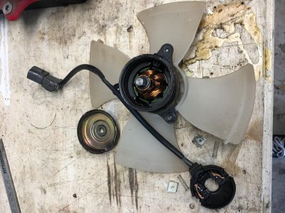
After some troubleshooting it appears that I have 2 dead AC Condenser fans. They're $250 each from Acura, so I have one of them out and torn down on my work bench.

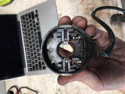
1. It appears that those brushes need to be replaced. According to calipers they are .23" or 5.8mm square, but I don't know the length. Can I guess an approximate length and be ok?

2. What else should I do while I have this motor torn apart? Cleaning, oiling, etc.

Speak slowly and use small words, this type of repair is new for me =)

Thanks!

EDIT: In this thread about a seat motor [MENTION=7701]Oldguy[/MENTION] says to see if the commutator is worn down, check to see if the windings are ok, and that there isn't bridging int he commutator segments. How can I do these things?

IMG_6330.jpg

IMG_9773.jpg
IMG_6797 2.jpg
IMG_0624 2.jpg
 

Attachments

  • IMG_9773.jpg
    IMG_9773.jpg
    188.7 KB · Views: 528
Last edited:
I've never taken either apart but the engine bay fan motor looks almost identical to the a/c condenser fan motor. If you have an early car and still have the engine bay fan fitted, it may be worth a look for comparison or spares?
 
This is the commutator (circled in red).

Rad fan motor rotor.JPG


Considering the wear on the brushes, your commutator looks to be in quite good shape. The dark area on the commutator is the contact area for the brushes. Typically, after a lot of use you may develop a circumferential ridge between the dark area and the bright copper area of the commutator segments. Worn commutators may also develop circumferential grooves / gouges / scratch like marks in the dark area where the brushes contact the commutator. The correct fix for the ridge and circumferential scratches is to place the rotor in a lathe and turn down the commutator so that it is smooth and remains circular.

In the photo, I don't spot a wear ridge and I don't see any obvious scratches. As such, I suggest start with a simple cleaning to see how it looks. Use some electrical contact cleaner (best) or perhaps some 90% IPA (second choice) and a Q tip or really soft brush and wipe along the commutator segments to remove contamination on the segments. Stay away from chlorinated / organic solvents (toluene, xylene ...) because they may damage the varnish insulation on the winding. If the commutator cleans up nicely, stop there. If there are some fine marks, you can try cleaning up with something like 800 - 1000 grit Al Ox paper. This is tricky because you have to be super careful that you don't get the commutator out of round with the paper. You can try using a drill to do this as shown in the picture below (that I scored off of some internet site that I can't remember). I wouldn't do this unless you think it is absolutely necessary because things can go bad quickly. After you do this you will need to clean everything up again to remove any copper filings.

cleaning commutator.JPG

Once the commutator is cleaned up, check the gaps between the commutator segments looking for bridging. The green arrow in the first photo points to the gap where you want to check. From the gaps that I can see I don't spot any obvious bridging.

Checking the rotor for insulation failure or broken windings is difficult. Repair shops use something called a growler - literally because it generates a growling noise if there are shorts. Doing checks with a ohmmeter is feasible; but difficult because you are trying to detect small differences in very small values of resistance. Typical digital meters lose the difference because they generally are not able to measure low values accurately. A basic check would make sure that the resistance between any of the commutator segments and the shaft of the rotor is infinite. A short means an insulation failure which requires a rewind of the rotor.

As to the brush length - I have the really useful comment 'longer than what is in there' :smile:. I think it is going to be a case of going with what you can find. Stick with the original springs. They are important because they establish the correct contact pressure between the brush and the commutator. The new brushes should not be so long as to create coil bind on the springs. When installed, you want a small amount of room to allow movement of the brushes in the holder. If anything, err on being a little shorter than too long. The curvature on the brush should / must match the curvature of the commutator.

In the top photo is that a broken shim? The rotor should be shimmed to prevent the rotor from moving in and out during operation.
 
This is the commutator...I suggest start with a simple cleaning to see how it looks.

Done. Cleaned with 91% IPA. I don't see much of a ridge, but do see some light scratches, don't think it's worth breaking out the drill. Here is how it looks now-

IMG_3664.jpg

Once the commutator is cleaned up, check the gaps between the commutator segments looking for bridging.

Done. I cleaned out some carbon dust from the gaps with a razor, no sign of bridging.
Checking the rotor for insulation failure or broken windings is difficult.

Skipped this. I'll order the brushes and focus on re-assembly.
A basic check would make sure that the resistance between any of the commutator segments and the shaft of the rotor is infinite. A short means an insulation failure which requires a rewind of the rotor.

Done. Infinite all the way around.

As to the brush length - I have the really useful comment 'longer than what is in there' :smile:.

Hah! I just ordered two sets from Eurton Electric, I'll post the part numbers here when I'm done. FYI, Eurton says they can repair/re-wind these motors for $175. More cost effective than Acura, but still silly if the brushes are all that is needed.

In the top photo is that a broken shim? The rotor should be shimmed to prevent the rotor from moving in and out during operation.

Good eyes. If I understand the shim arrangement all the shimming is set at the opposite end of the motor-where the fan attaches and there are a couple metal shims/spring washers. I think the broken plastic washer that you see was a dust barrier between the circular plastic plate that carries the brushes and the end cap for the motor that houses the bearing. I don't see how it could be a shim because the motor shaft will bottom out on the motor end cap before the shim/dust barrier could stop it.
 
I've never taken either apart but the engine bay fan motor looks almost identical to the a/c condenser fan motor. If you have an early car and still have the engine bay fan fitted, it may be worth a look for comparison or spares?

Ha! It sure does. Yes, I still have the engine bay fan. Different part numbers from Acura (similar price though!), so I assume there is some difference. The fan blades are different as well.
 
Ha! It sure does. Yes, I still have the engine bay fan. Different part numbers from Acura (similar price though!), so I assume there is some difference. The fan blades are different as well.

If you are up for an experiment, assuming that the motors are similar it might be worthwhile to open up the engine compartment fan for the purposes of examining the brushes. My understanding (since my 2000 lacks the fan) is that the engine compartment fan operates infrequently so the brushes should be close to 'as new' which would provide a better estimate of the correct length than my 'longer than what is in there' comment. Making sure that the new brushes are not too long is important since excessive spring pressure will cause high initial brush wear and contribute to higher commutator wear.

It is interesting to note that in your second photo in your original post, one brush is worn much more than the other. I am assuming that you plan to do the other condenser motor. If so it will be interesting to know whether this differential wear is unique to this motor or is a common feature. Make sure that both brushes move back and forth in their holders freely and that it was not a sticky brush holder that contributed to this differential wear.

Good eyes. If I understand the shim arrangement all the shimming is set at the opposite end of the motor-where the fan attaches and there are a couple metal shims/spring washers. I think the broken plastic washer that you see was a dust barrier between the circular plastic plate that carries the brushes and the end cap for the motor that houses the bearing. I don't see how it could be a shim because the motor shaft will bottom out on the motor end cap before the shim/dust barrier could stop it.

In normal operation, the fan will generate a longitudinal force which pulls the rotor towards the fan blade, so you are correct that any shims that have to bear thrust will be on the fan end of the motor. So, once in operation the front shims / thrust surface combined with the force generated by the fan will hold the rotor in position. When the motor is assembled, is there something on the fan end that prevents the shaft from moving back and forth in the bearings? If so, then that 'shim' on the commutator end may just be a dust shield. However, without seeing the motor, I don't understand the comment 'because the motor shaft will bottom out on the motor end cap before the shim/dust barrier could stop it'. I would have thought the purpose of the broken spacer would be to prevent the black plastic portion of the commutator assembly from coming into contact with the rear bearing. If something on the fan end of the shaft captures the shaft preventing it from moving back and forth in the bearings (when not in operation), then the spacer may not have an important function. If when assembled the shaft has some back and forth movement in the bearings I think it would be beneficial to find a replacement spacer to eliminate that movement and maintain the correct position of the brushes on the commutator at start up.
 
Nice post and good DIY. Saves some serious $$$.

If so it will be interesting to know whether this differential wear is unique to this motor or is a common feature.
This is quite common in high current scenarios. I've seen it in all kind of electric motors that contained brushes. One was worn more than the other. You can also notice it in a starter when you change the plunger and copper pieces.

Keep the good work going...
 
Yeah, you are doing this all correctly; you have likely found your problem, it is easily and inexpensively fixed.


The length of the new brush doesn't have to be precise, just as much as you can fit in there without binding the motor, or less. Old Guy is right: more than what you have now.

What does need to be reasonably precise is the fitting of the brush in the slide. Too big and it will bind on the sides with too much friction and too small it will get cocked or make contact with too much of the commutater. There are shops that will make custom brushes for reasonble money, in fact you could probably do a Group Buy and supply everybody with new brushes. With any luck Honda chose a common motor and parts will also be common; Honda likes to do Parts Bin Engineering and we should appreciate that.


The blower motor for the climate control also wears down the brushes. Heck, take a look at that too if you are up for it.
 
Last edited:
The nice thing about the brushes is that they can be easily made fit to the required dimensions as a DIY if they're a little bit too wide, tall, height or whatever. The have the consistancy of chalk.

Make sure to grind down any sharp edges between the copper elements you see in the picture in #4 above or your new brushes won't last very long.
 
Last edited:
I think the biggest potential issue with the new brushes may be matching the radius of the contact area of the brush with radius of the commutator. If the brushes that @SWFL_NSX ordered by some fortune have the correct radius, that would be a home run hit. However, some of the brushes sold by Eurton have no radius on them or no perceptible radius. Installing a brush with no radius on it means that the contact area between the brush and the commutator is going to be smaller than the design value and as a result the current density in the contact area is going to be much higher than normal. This will likely result in burning and pitting of the commutator which may bring motor operation to a premature end. At that point the motor would require a trip to somebody with a lathe who could machine the commutator and return it to newish condition.

This web site talks about the process of bedding in new brushes.

http://carbonbrush.freeservers.com/bedding.html

I expect from their description of the process and the grits that they recommend they are describing a process for use on large commercial / industrial motors - something where you can get your fingers in the housing to hold the paper and pull it back and forth under the brush. Not really applicable to the small condenser fan motors. I think you will get the idea of the process from the description; but, you will have to improvise a technique to do it on these small motors.

They refer to using glass paper for the abrasive. I expect that they mean Si carbide or Al Oxide. True emery paper is to be avoided because it contains metallic abrasives which would mess up the commutator; however, I am not sure that anybody makes true emery paper anymore. In my opinion, starting with a #80 grit would be a no go. Given the size of the brushes in the motor, I would be more comfortable starting with something in the #300 - #400 range and then finish off with some passes of #600 .

As to @goldNSX 's comments, if any of those edges project above the commutator surface, they must be removed. Rough edges at 90 deg to the commutator contact surface are undesirable. On an industrial DC motor the commutator bars would have a tiny 45 deg bevel put on the edges of the bars. I don' think that is practical for a motor this size. I am personally leery about trying to remove any roughness on the sides of the commutator bars in part because I can't think of a handy tool to get in there to clean up the slots.
 
Last edited:
Old Guy, you are correct in theory. And it is desirable to have bedded and fitted brushes...

In practice, on low current motors like this my experience it doesn't seem to matter much. I've replaced a few dozen motor brush seats and never seemed to have a problem, even after 20+ of grueling use on vacuum, drill and saw motors.

The brushes are wide and should wear down fairly quickly to a comfortable shape. I would personally just install them, however, Old Guy brings up valid points.
 
As to @goldNSX 's comments, if any of those edges project above the commutator surface, they must be removed. Rough edges at 90 deg to the commutator contact surface are undesirable. On an industrial DC motor the commutator bars would have a tiny 45 deg bevel put on the edges of the bars. I don' think that is practical for a motor this size. I am personally leery about trying to remove any roughness on the sides of the commutator bars in part because I can't think of a handy tool to get in there to clean up the slots.
I'd give it a try with an appropriate dremel tool by grinding in an angle of 45 degrees. It should remove the undesired sharp edges between the commutator segments, but really just the sharp edges, nothing more. In the lack of a dremel one could try it with sanding paper which should fit quite easily between the segments.

I agree that the radius should be 'about' the same but it doesn't have to be 100 %. It's like new brake pads on old discs, time will even them out quickly as long as you adjust the shape of the pads by let's say 80-90%.

If you testrun the motor overnight you can always check back before you finally mount it back on the car. You could remove the brushes once again and check their (new) shape, personally I wouldn't. I've changed brushes several times and never had a problem in the longrun.
 
My indirect experience has been with large high value electric motors where brush set-up was a religious ceremony. If others have direct successful experience with sticking unbedded replacement brushes into these small motors, then I will defer to direct experience.
 
When my car was being repaired by Joe Lomoriello, nearly 2 years ago, the a/c condensor fans were not available new anywhere (not even in Japan) so he took mine to a place in Poughkeepsie to be rebuilt but it didn't last long at all. Fortunately, my local Acura dealer had put the motors on critical back order so Honda ran a new batch. I've see a couple on eBay for about $240.
 
Thanks for the advice everybody. The fan is reassembled and has been running on a test battery for an hour or so. There is a slight ticking that I didn't expect (too quiet to capture on a movie), but there are no vibrations and it seems to be operating normally. I'm going to reassemble this afternoon and will update this thread if anything else happens to the fan during my ownership.

If anybody sees improvements to be made, feel free to comment. I didn't clean up the commutator in any way beyond the 90 IPA, or bed the brushes, or find a new dust shield. I plan on doing these when I rebuild the second one, but just didn't have the parts or time this week.

Parts:
Brushes Part number: I used Eurton part numbers 33-6612, 6mm x 6mm x 12mm. These brushes slid easily and didn't bind when the springs were inserted into the housing.

Mushroom Crimps: I had to re-use the existing crimps, if anybody knows what they are called let us know!

This picture shows the shim arrangement at the right side of the rotor and on the right side of the rotor housing. When this section of the motor is assembled it prevents the rotor from moving back and forth (longitudinally) in the bearings (@Old Guy I hope I'm making this clear).

IMG_2872.jpg

Here is a close-up of the new brushes as well as the crimps that attaches them to the existing wire. You have to re-use these crimps because of the unique way they fit in brush holder. If anybody has seen these for sale let me know and I'll include the part number in this post!

IMG_5112.jpg

Put the brushes into their slots in the brush holder and make sure the t-crimps are in their slots as well.

IMG_1776.jpg

Here is what you should have at this point-assembled rotor and rotor housing, brushes inside the brush housing, springs and caps not yet inserted, and the cap.

IMG_5342 2.jpg

Next steps-put the brush holder (including brushes) on the rotor assembly and make sure it is aligned correctly and lying flat. After that, insert springs and the white spring covers, allowing the springs to push the brushes into the commutator. Be careful that you don't move the brush holder too much at this stage as it will result in springs and covers flying all over the place.
IMG_7386.jpg


Make sure the rotor is aligned in the middle of the housing, and put the cap back on. You may need to hammer out the divots in the cap before putting it back on...do not try to hammer or force the cap back on the motor! After that, use a hammer on the three areas of the cap lip that seal the cap to the body of the motor.

Test the unit.

I also used this opportunity to clean the condenser using an AC condenser cleaner. I'm not sure how effective this is, but the cost was minimal.

IMG_6519.jpg

Hope this helps somebody in the future!
 

Attachments

  • IMG_9704 3.jpg
    IMG_9704 3.jpg
    298.7 KB · Views: 242
Last edited:
Thanks for the updates. I'm wondering how long it lasts (pretty sure long...). Your attachments don't work...
 
Excellent follow up and thanks for the part numbers for the brushes.

It looks like you did the reconnection correctly and your testing would have confirmed this; but, for anybody considering this its worth repeating that the blue/blk and the blk wires to the brushes must go back into their original positions in the motor. Otherwise you will switch your fan from suck to blow mode greatly reducing its effectiveness.

The cleaner definitely will not hurt. From personal experience it is the dead grasshoppers cooked into the fins on the front side that is the greater impediment to the effectiveness of the condensers. A fin comb is your friend there.
 
Pics now work, thanks, great write-up.

Cleaning the condenser is a good idea. ETCG once did a test and found an impact on the system. It doesn't get cooler in the car overall but the system pressure was about 2/3 of that before after cleaning the fins with a chemical cleaner and spraying the hell out of the fins in the opposite direction. Such a service every 5 years is recommended when you love care about your A/C system.
Video here: https://www.youtube.com/watch?v=r_em9lm69HQ
Same for the coolant radiator too.
 
Just finished rebuilding the second fan-quick notes and a question.

1. Yes, one brush was shorter than the other on this fan as well. It seems this is the natural wear pattern for these units.

2. The dustcap is built into the brush housing on this fan-slightly different, likely updated design.

3. When removing the fan housing from the car, the housing must drop down to clear the suspension.

4. This time I had this commutator "cleaned up" with some emery cloth by a shop that rebuilds electric motors, alternators and similar. Not sure if it's related or not, but the very faint "clicking" is gone from the second rebuild.

Question-

I just turned the car on to check the function after installation. I was surprised to see that both fans blew out the front of the bumper instead of out into the wheel well! After reviewing multiple pictures I took of both fans during disassembly and reassembly I'm certain that I have the wires oriented correctly in the fan housing.

Is it normal for these fans to blow out the bumper? If not, what could I have done incorrectly?
 
1. Yes, one brush was shorter than the other on this fan as well. It seems this is the natural wear pattern for these units.

Is it normal for these fans to blow out the bumper? If not, what could I have done incorrectly?
1. That's with all brush type electric motors, the one facing + will always wear out faster.

No, the car won't reach 168 mph anymore. :D I've no idea what went wrong but the fans MUST work the opposite way. Are you sure it blows out of the bumper and it's not vacuum you feel? Try with a candle.

A simple fix would be the change the pins before you open the motors again.
 
Are you sure it blows out of the bumper and it's not vacuum you feel? Try with a candle.

Ah! This was it exactly-when I put a candle in front of the bumper I could clearly see the direction of the air flow back toward the condenser and fan. From the wheel well side of the fan there is very little air movement except around the outer edge of the fan.

Thanks!
 
You're welcome! :)

The fans are just there for speeds up to maybe 20 mph. Above that speed the air flow is strong enough to cool down the condenser.
 
After some troubleshooting it appears that I have 2 dead AC Condenser fans. They're $250 each from Acura, so I have one of them out and torn down on my work bench.

1. It appears that those brushes need to be replaced. According to calipers they are .23" or 5.8mm square, but I don't know the length. Can I guess an approximate length and be ok?

2. What else should I do while I have this motor torn apart? Cleaning, oiling, etc.

Speak slowly and use small words, this type of repair is new for me =)

Thanks!

EDIT: In this thread about a seat motor [MENTION=7701]Oldguy[/MENTION] says to see if the commutator is worn down, check to see if the windings are ok, and that there isn't bridging int he commutator segments. How can I do these things?

So I recently got 2 new condenser fan motors in from Japan. I didn't have the time to do your rebuild. Do you happen to have a link or info on the process of replacing the fan motors please? Been searching but haven't found a DIY for just replacing these motors. Thanks!
 
So I recently got 2 new condenser fan motors in from Japan. I didn't have the time to do your rebuild. Do you happen to have a link or info on the process of replacing the fan motors please? Been searching but haven't found a DIY for just replacing these motors. Thanks!

Not too difficult. I went in through the wheel well for both.

Steps-

Losen lug nuts
Car on Jack stands
Remove wheel and fender liner
Disconnect wire connector
Might have to fiddle with the connector bracket, can't remember
Remove fan and housing
Remove fan from housing

Stuff to have on hand-

Good assortment of extensions and wobble heads
Spare wheel liner clips and fasteners

The fan and shroud have to come off together, getting them out of the wheel well requires some spatial reasoning (or luck). I remember that the housing has to drop down to clear the suspension, but that it clears it without having to modify anything. Having the extensions on hand is critical-you'll have to get a socket/wrench on both sides of the housing to remove the bolts. The bottom housing bolts will be corroded, I cleaned mine up with a tap and die before putting them back on.

Here is a link to info on wheel liner clips and fasteners-http://www.nsxprime.com/forum/showthread.php/206988-fender-liner-fasteners?highlight=wheel+liner
 
Back
Top