Now that I'm nearly retired, and after 8 years of being frustrated by the interior-dim problem, I decided to make D'Ecosse's 3/18/2006 circuit (the more complex one) work in my car. It is a 100% success after a few minor, but very important, changes. The switching is very clean - no flicker when going under bridges, etc. (So as a retired electrical engineer, I haven't lost all my design skills yet. :biggrin

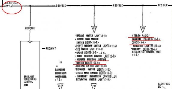
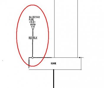
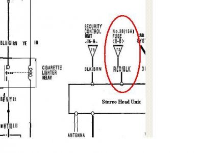
I built the module so that the cable that went to the clock goes into the module. The module then has an output cable that goes to the clock. One new lead from the RED/BLK leads at the connectors to the ACCU and radio plug into the module. And there is an input connector from the LDR.
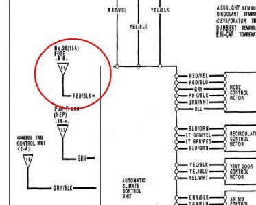
As noted in his updates, the output goes to the RED/BLK lead on the ACCU (AC control unit),
not to the red lead. In addition, I added a 1 Kohm resistor from the NC contact of the relay to ground. This guarantees a ground on the controlled red/blk lead when lights are off or it is bright outside. (Other dash lights, etc provide that function when all the leads are connected together. With this control circuit added, it is possible for the clock to leak enough current into that lead so that the radio lights come on even with the car off. The 1K ohm resistor bleads off the leakage current).
And finally - the key modifcation that caused others fits: You need to insert a diode in series with the RED lead on the ACCU. I actually did this inside the ACCU. No board modifications were needed; there was a convenient wire to cut and insert the diode.
One remaining problem to solve :redface:: finding a path underneath the dash board to install the LDR (light sensor) in the front of the dash near the light sensor used by the ACCU. So, for the moment the lead to the LDR comes out of the console at the top of the clock and is lying on the dash.
QUESTIONS:
1. Is anyone interested in my final schematics and seeing my installation pictures?
2. Does anyone know a good sneak path for the LDR to get to the clock connector area from around the defroster vents & ACCU photo-sensor at the very front of the dash?
Frank
'96 NSX0-T, red/tan
PS: My '84 Corvette came equipped from the factory with this type of automated control on the readouts, so it was obvious there was a reliable solution for the NSX. I just didn't have the time before to dig into this. It took days to measure the characterisitcs of the clock, radio, and ACCU, try various alternatives, then come up with the two simple but not so obvious mods. Building & installing the circuit was the easy part.
I first attempted to use the factory photo-sensor for controlling the ACCU, which detects high levels of sunlight and adjusts the AC fan speed etc in anticipation. However, that sensor had too little change in output voltage at the light levels where the dim/no-dim decision needs to be made. I amplified and level shifted the signal, but the voltage variations were still too small to reliably detect over full temperature range. So, it was back to using a separate LDR


