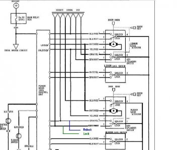
Anyone know what site i can go to, to see a schematic of the wires for the 1991 nsx? Im trying to install a new viper 791xv 2-way remote lcd alarm system, and need the wire diagram to the nsx. thanks...
You are using an out of date browser. It may not display this or other websites correctly.
You should upgrade or use an alternative browser.
You should upgrade or use an alternative browser.
schematics for alarm system?
- Thread starter R3DLINE
- Start date
Here are some notes I made and I'll edit it to add more information as I can find it. I'm just missing the unlock and lock as well as the parking lamp. The unlock/lock can be tricky depending on the alarm. I think D'Ecosse can elaborate on this. This information can all be found in the service manual, all the pages I referenced came from a 95 service manual.
Wire/NSX Wire/Factory Manual Page #/Wire Location
Ignition 12v/Black Yellow/23-72/Driver side/Ignition Switch Harness
Power/12v at battery/N/A/Take 12v wire directly from battery
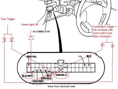
Negative door trigger/Black/White/23-150/Safety Indicator harness in Gauge assembly
Negative door trigger alternative - Wire left and right doors together with diodes from the Secuity Control Unit
Trunk Trigger/White/23-321/Security Control Unit Harness
Starter Kill/Armed Output/Black/White (Cut starter wire)/23-72/Driver side/Ignition Switch Harness
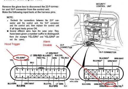
OEM Factory Alarm Disarm Output/Green/Yellow #1/23-322/Security Control Unit Harness
Negative Trunk Output/White/Red (Will need a relay to convert to + out)/23-253/Driver side/Trunk Switch
See my post on safely wiring up the remote start using the neutral switch and bypassing the clutch switch, which should be useful:
http://www.nsxprime.com/forums/showthread.php?t=41381
All the connections for that part should be available in that post.
Some other wiring connection suggestions:
(see the on-line manual - http://www.nsxprime.com/FAQ/Reference/1991_svcman/1991servman.pdf -page reference listed for your convenience)
Starter Cut : Blk/W from IGN switch
IGN1: Blk/Y from IGN switch
IGN2: Blu/W from IGN switch
ACC: W/R from IGN switch
Door triggers: Gn/Bl & Gn/R (tied via diode) - page 1134
Hood/Hatch/Trunk trigger (tied via diode) - Gn/Blk & Blue - page 1134 & Y/Gn2 - page 1296
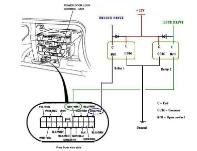
Unlock - W/Y - page 1240
Lock - G/W - page 1240
Note: you may have to use relays to operate the door locks consistently - with the Viper it might not be necessary but with the Crimestopper it is.
Also, by using the G/W for the door lock, this will also arm your factory alarm for added protection.
Dome light - Blk/W at safety indicator plug - use diode - page 1134
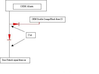
Factory alarm disable - Gn/Y via diode - page 1296
Also you need to cut the Gn/Y wire & hook up the connection viia diode as per diagram below
Most of the others should be fairly easy to track down, but if you have any other specific inputs you need, let me know
Good luck!
Attachments
hey guys, I really appreciate all your help. Imma gonna get started asap, but if I run into any problems I know i can get some help from ya. Thanks.
I'll be stripping the car so it would be easier to do, I need to install all my new stereo equipment anyways.....
just wanted to ask... do ya have the trunk hooked up so that you can pop it at a touch of a button?
I'll be stripping the car so it would be easier to do, I need to install all my new stereo equipment anyways.....
just wanted to ask... do ya have the trunk hooked up so that you can pop it at a touch of a button?
Yeah the way I wired my trunk pop was this. I took the power from the on/off trunk switch in the glove compartment to power the relay. Doing this, if the trunk switch is in the off position, the trunk cannot be opened from the remote since the relay will not have power.
Most brains will fit in the cavity above the security control unit.
Most brains will fit in the cavity above the security control unit.
Malibu, I know what your intention was, but it might be a little confusing to others - you cannot actually use the connection at the switch to "pop" the trunk from the Alarm O/P (via the remote) .... I think that your intention is to just use that as the relay power, so it is disabled per the condition you specified. I know you know this, but from a third party it might not be quite clear.Malibu Rapper said:.... I took the power from the on/off trunk switch in the glove compartment to power the relay. Doing this, if the trunk switch is in the off position, the trunk cannot be opened from the remote since the relay will not have power....
The O/P driving the actual trunk solenoid (via relay) still needs to feed the actual supply for that - different locations available, but you can pick this up in the harness that runs down the left side of the floor sill. A connection at the switch in the GB will not supply the solenoid directly because it's before the door switch in the cct.
Yeah, what he said. 
Power the relay with the glove box switch using the wire that is fed power by the switch (12v when in the on position, 0v when in the off). This keeps the effectiveness of the glovebox switch so that when you hand the keys over to the valet (with your valet key hopefully), they cannot open your trunk with the remote.
On the + output coming from the relay, you want to wire that to the white/red wire you can find where D'ecosse mentioned. When that wire gets fed 12v, *POP*.
I had a request from a member regarding using relays for consistent lock/unlock function - appears he also has the problem with his Viper alarm.
Also, by using these inputs, rather than those in the earlier post, the OEM security system will also arm simultaneously, for additional protection (and of course the security indicator light on the drivers door wil also flash)
Thought I'd share it for all:
Please note there is an ERROR on the circuit schematic in the on-line manual - it shows the wrong colour wire on the right key-cylinder lock switch. I have corrected it in the attached diagram below.
The diodes are probably overkill on these small relays and would work fine w/o them:
Parts required are easily obtainable at Radio Shack:
Radio Shack Catalog #: 275-241
Radio Shack Catalog #: 276-1101
Attachments
THANKS DECOSSE...This should fix my problem. I will let you know how it turns out!!!
Kevin
Kevin
Similar threads
- Replies
- 15
- Views
- 534
- Replies
- 0
- Views
- 224


