Remove rear axles.

Bringing this thread back from the dead again to ask:

Where do you buy the special tool for tightening the new bands? Honda or any old auto parts store? TIA!

EDIT: Got one from NAPA, will this one do the trick?

CV_Boot_Clamp_Pliers_Auto_Repair_Tool.jpg
 
Last edited:
Does anyone happen to have photos showing the specific items that need to be removed in order to remove the axle?

1. Large 36mm nut in the center of the hub
2. Rear Rod Beam (Big U shaped aluminum member under the engine)
2A. You need to separate the toe link from the rear beam by removing the one bolt at the rear beam end. No alignment here, just reassemble.
2B(optional). I remove the bolts (4) that hold the rear stabilizer bar so it hangs free, and then I remove the lower shock bolts. You may get away without this, but I do it so I can easily move the rear knuckle around, insurance to not damage the seal in the trans when you pull the shaft out on the left side.
3. Lower a-arm inside mounting bolts (including camber adjustment, mark it)
4. The two lower shock mounting bolts and sway bar mounting bolts (I pull the sway bar back and out of the way to make it easy to swing out the rear knuckles, especially on the drivers side.)
 
I do not, but I have a tip for #1 fwiw.

Jack up car
Remove wheel
Un-stake the nut
Remove the center cap from the wheel
Re-nstall wheel and put the car back on the ground
Engage the e-brake
Use jack handle as a cheater bar for the nut.
If you use a 1/2" breaker bar make sure it has a lifetime warranty.


Does anyone happen to have photos showing the specific items that need to be removed in order to remove the axle?

1. Large 36mm nut in the center of the hub
2. Rear Rod Beam (Big U shaped aluminum member under the engine)
2A. You need to separate the toe link from the rear beam by removing the one bolt at the rear beam end. No alignment here, just reassemble.
2B(optional). I remove the bolts (4) that hold the rear stabilizer bar so it hangs free, and then I remove the lower shock bolts. You may get away without this, but I do it so I can easily move the rear knuckle around, insurance to not damage the seal in the trans when you pull the shaft out on the left side.
3. Lower a-arm inside mounting bolts (including camber adjustment, mark it)
4. The two lower shock mounting bolts and sway bar mounting bolts (I pull the sway bar back and out of the way to make it easy to swing out the rear knuckles, especially on the drivers side.)
 
I'm in the middle of repacking my drive shafts and didn't remove the rear beam. I disconnected the lower control arm from the beam. Really I think I just followed the steps in the service manual.

My axle nut came off fairly readily with a 1/2" air- impact gun.
 
Last edited:
My axle nut came off fairly readily with a 1/2" air- impact gun.

Mine laughed at my 1/2" impact gun. Then I purchase an electric one, thought it'd have more torque.....not so much. :)

I finally got it and then upgraded to a 3/4" breaker bar which is still going strong.


Was almost as tight as the nut of death on my 63 karmann ghia
 
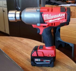
Here's all you need for removing the axle nuts. Milwaukee 2763-20 This thing is awesome. I think it would work, even if you left the nut staked.

attachment.php
 

Attachments

  • Impact.jpg
    Impact.jpg
    49.4 KB · Views: 1,001
Last edited:
A good impact gun (3/4" or 1" drive) is the answer. I used my 3/4" breaker bar with a 6' pipe over it & that worked well, too. You'll need a 3/4" torque wrench (or a torque multiplier) to install the new nuts to spec.

For dlynes, just follow the manual (downloadable from NSXPrime). But, I had to remove a few extra suspension bolts to get enough clearance to remove/install the left (driver's side) half-shaft.
 
Last edited:
yes, remove the u-shaped brace

I'm in the middle of repacking my drive shafts and didn't remove the rear beam.
Well, I'd like to correct my stupidity. I was looking at my car yesterday and decided that removing the brace--the "Big U shaped aluminum member under the engine"--makes a significant difference to getting the driveshafts in and out. So I took it off and getting the passenger-side shaft back into the upright and intermediate shaft was so much easier. It really quick to remove the brace; I have learned something.
 
For dlynes, just follow the manual (downloadable from NSXPrime). But, I had to remove a few extra suspension bolts to get enough clearance to remove/install the left (driver's side) half-shaft.

I've searched WIKI but I did not find where I can downloan the PDF. I saved it many years ago but it's on an old external hard drive somewhere. I was also able to remove my axle nut using cheap harbor freight 1/2 air impact gun.
 
Just wanted to say thanks for all the folks who contributed here. This thread, Kaz's post, and the service manual and made this a pretty easy weekend project and I am very pleased with the end result. Happy wrenching all.
 
Thanks MJK for sharing the link to Kaz's post. I'm about to refurbish my axle boots, so all these clues from Larry and Kaz are very helpful.

Curiously the Service Manual doesn't mention a band tensioning tool, whereas both this thread and Kaz's suggest it's quite important. What did you use to tension your bands?
 
Last edited:
Do you really have Porsche brakes on yr NSX? Must have been some clever adaptation as they have a totally different stud pattern ...

Yes calipers from a 997S and custom top hats and brackets by Titaniumdave (who made them for himself) with rotors from Coleman. Dave does great work. They feel and work great but it makes for some challenges fitting wheels over them.
 
Thanks MJK for sharing the link to Kaz's post. I'm about to refurbish my axle boots, so all these clues from Larry and Kaz are very helpful.

Curiously the Service Manual doesn't mention a band tensioning tool, whereas both this thread and Kaz's suggest it's quite important. What did you use to tension your bands?

Correct about the 1991 manual; but, I believe the later manuals have a reference to the tool. I seem to recall a picture in my 1998 - 2000 manual which showed the use of the tool. I think it even included suggested (non Honda) part numbers for the tool.
 
Yes calipers from a 997S and custom top hats and brackets by Titaniumdave (who made them for himself) with rotors from Coleman. Dave does great work. They feel and work great but it makes for some challenges fitting wheels over them.

Radical ... and I know what you mean about challenges. I fitted the big stoptech's on mine. Barely a few millimeters to spare everywhere. Had to choose rims carefully to suit calipers and then had to center the caster setting so the wheel would not scrub inside on full lock, even using 215/40R17 tyres. But they work a treat, and I reckon they look like they came with the car as OEM brakes.

NSX Stoptech brakes - front.jpg
 
Dragging this post back up from the depths. I got stuck removing my LH (US driver's side) axle at two points last night. First, there appeared to be no way to get my prybar and large flathead screwdriver to be 180 degrees apart on the transmission. The trans itself shrouds about 180 degrees of the joint. Instead of the pry bar, should I use two screwdrivers? I have two very large flatheads with long handles. Do I just put them in as far apart as possible and whack one with a hammer? It's an auto trans if that matters.

Second, both axles are rusted in the hubs pretty good. I tried to whack them with my 1lb hammer using a wood block and they just laughed at me. Any ideas? Do I need "more hammer"? Does PB Blaster work here? It seems like the horizontal orientation of the joint would not allow much to soak into the splines?
[MENTION=3729]Larry Bastanza[/MENTION]?

You can see where I was prying with my prybar below.

7q2wbck9V5KQk4eivcOrzMFOjfDZDL3e4HiYLQY1MzfSqyQf47MwhVV8julYiJNWT5okxQ4Y6LtDRSdm2ucjYi2WypN2Jlz5c7g3YjtOkJP0KyTV74ly_vNUxiaOE8d0morr75zzweG2-QIMF7w9OuVLWbxgvC79XCp1DD9B98fpXYcSRlLHDkLCAQj8Herv76eN4Xj672uOWgcsivxNtwGc2W3tJzqUIEWj-n3SWg6Ob51_2B81qZm2Mxb9TBUxwH8Sb4sJlxiO4vwi3sDscHlKbMmLtWw5rAWlO6dOVPjJ-iE8lb3RqqUuATWGtJFwGg34aMhKoSbV3AxDQpRhKjc38URao9XDn6MLZE2nyvYX3Qnz9VF09SnRmvWzUGxdGIuteL20J4T8oNXePZiEC8pD88CjBseZxUApd2pH4cOnlCoBTJ-wjwvGE5tcqlT4OcyLvBU7e-pWVdJYN30tk_rIDqUMO2v3lJ92YBl8cERgmAGxQ1Uu2PVVPZ0P0y3luqzMv0G_onbNHVZE_87aynDKYbuKSzDpv2e8T5s0JdpHGZfwnlppUVLbxzG_3Pjq_iO0WcMIGC2tYTD9_g6ixhtfvznVWGu9uLiL8D5gHPE9O5NbcIZvD4sixHB7KXB-hCFOQG9-Gh1r8avd0fc3LhMGMz6RqXnw6rse4jp3PWNTOiAYk1nA9BZhfZMZpYLJBm8lXFliXjmb53K0POaXZ-WvOi7gjXmYNqvHfbxN9soLFA0c=w973-h1297-no


xVBKuxOiSYLFnlN1f5pMn1Adin027sI08kh_wLlQCPamZmnWJYhCTgpIeH_T5vGsriSSIB2g9vCEsv9M8afZ3a5YcAav8gnYnV_AIU-__1kNgWWl6hohGwkBwoAJdrEmP9pNtBVWi74WJMgopbwjpL420AH-4cagJamxBkl4rpZzCAjw_bKGJUF9vZ2V--QOyhLQJ9g6tw34Q6iF_CaarE0vwNdZJcmdAJg8I9NRPPmcNCql8xMZKrPrCX9AN8tXRDpm6Uj48VDzEOwAZy4xezi_fZQ-HIuQQ3nj1-QKxQNaoXkAkPE81x7_bZacNX-b6lLydvA-IpYLpjsMZM_LdK41nT_O2oNCP99mzMFwNx7YHPJHZwbhIymvaQrsDKCR34zQ4j22WEWFT_X5lfKplfmHXyLgFSwx2dP4G3KxUj5hZEoFzI36jFAksrXbiuOvPtHJOKMHnI2MoHU1jZp_6JdNqDLDf1x47tTgMmUy_Pdq8uvYs-Qp93mUNO5GVY9n2_CR8uifJRbyGx1OO5dRUZDCF96kiVyW1425llf5e5FR0Me6i3lM3ZS1LLgHRyqraDYFEWMA9fFv87hFSFtfMtZw944sYiBuvb-5ML8qMGS4qf3zsGbBjJzeGcXUm_HY5wKapVIQh55VDfmLeLq4LAsh20jksCSOFKinTUfSeFsNsiFOrvYfDVfKGIkxOHtwJIbBs1O3Qx9_zTT0emfCy18ZAkLEZQeXuij0M9WnazoE80OU=w1730-h1297-no
 
Looking at visuals you may want to consider brass block and hammer. Can try spraying PB blaster with hope that it's going to penetrate some of the friction surface on the splines. But not a lot of room to access it, doable though. Don't forget to put anti seize in there when you assemble it back together.
 
>Instead of the pry bar, should I use two screwdrivers? I have two very large flatheads with long handles.

Yes. You should be able to wiggle the screwdrivers in as a wedge as close to 180 apart as reasonable.

I like to have a jack underneath the wheel with moderate lift to assist by giving a bit of play to the axle.

You shouldn't need a hammer. The AT comes out just like the MT.
 
I hammered on a brass punch like solidol recommended to separate the axle and hub.

Since you're dropping everything eventually anyways, why don't you remove the suspension and entire subframe together and work on separating everything when it's out from under the car. It's much easier that way!
 
lHq2XV0VyVdZcg0VGs8dE8VwVnh0EUXFIJIuS0X8_Pxr8y1SzyxwW-ccuk-OsdQJpABdkHVz-uW5Sj3UrQELNRZVk7oXwf7uWZV3yjMCS_EyrgafWFt6XArm9gJhxvC9CJufTRnVkjrpuRw3sLR7Lk00yaLv0TMYHz21vi5pAtvavH_86SsGzErlGyQCPAbFsIr4cIZje-pfzMERaNBDHiga7Xezy8HRq3AubXrnRlXS1oiQQts9WMH6tXD6TMNKPiCb2_TF2gfYVkCpSXgywRJmkRjz8Es7r5FPn472ZkUuGzVdLOXAq40v0xnwhXgIdHr8KkrG9L_eu9dgGJ0njLOweYAMySSKRFc4ijZiWsEENkwdMEEkFvuKvBOGWD6jYoZh7bh0c_1Sxqjpw8gCUozS8k5bFMXSEWLr4bG4sv7VHHUXOeUkZFG2tAaDnVZkWo8GP2JwZH6wkrByINijUs-jEQTYjnAOyDA_F3WaH29G5_w5ituETMrcnYDw4_SvC7vCR4ZvzWJeyQ4jh4qUtzEatFukDHBMxVmKMTzE_zIp2mc1d_ah88Rq-UGNfuk_nydLrf6IbbWmn-KbC0rSF66yF330f0iPGD-M_3xWZdlvQYOIHRgW7859fsiGNVoLU9pPyK7CiDQ2U6C5wuh030p4OX2V40gxel4xGR2nG05eOc7DRVws_rw0P7Ca4uYEKArTsyClRe8797JJrbu8isqC8Bs2PnzGlJ3AocBRlLVsbPuN=w1080-h608-no


g8tHbI9qdrrZBl4cNGO9ch9i6jlROvC11U8jzYJtjY_KemGgJnbLdCUPKaqAVHtHRs-3-bSyKOqXJbzvhjKE17M6C-uEPk376tLBfIdDYzjhbA_hJBTNQS-t61D3aCx-69dufKNsjQ9_0iQgR131c7ef_763lgE41GZFqB7tsFVX0K8BYA5ala_MWAO42XPHYuBXR-6DAErYkbZwv6KKZCR4rmXy2Oazr95bQgDL65OjBQGu4lJret1UBAZxK9O0-AMhivP0fqPp2owfhSuIZwxzY7uy1C4tAUieHb6Qh7x4yj-b6zNaY9ExvAAQVz1Qako0YQ0Xt42qdlSKRJUPWwZ20uHpZq-ytQqrHHPuq59Bihu4zEWSxpZWsYFMssMYWs0oRGlVYJF9dAXh_puLGTNqYSXatsWCQhPLrERatnki-eoPrUGMZXtFMCCrfx2YAeQD576fugtIGvWAB5uRmodoC6djLz6BzvE6_EJiITV7SmCCrid65hg5ov6_Zd6v-msgy7v6ZMFwAP6Sqbx44mmxxaxGhJPejLLYyW9nrav0v7NvTssOy1T2C6q1EBZhiNwhKssjuGkQdqhmJ24pPim975ZYGFKM4oiZfQTdZDBcIs_GRIxUcFh8KiwI5_QAa8sQZ8XaPoTImT8W9MlL5Sps1Wwc4klcW3PoAJHmipdJR7Y6ywtzYFaVWFEZjJCi1lEBn2KZA9ECgv-vCqKCbwc8ANDEhHWq27duSaHoTwaKbt-u=w1080-h608-no

This is MT but you should be able to get some idea.

Just try wedge in two flathead wide screwdrivers about 180deg apart, like marked in yellow.

If the joint housing doesn't pop out, rotate the wheel about 45deg and try again.
If it still doesn't work, repeat the 45deg offset again.

There is a C-ring locking the spindle shaft inside the DF so you just need to find the sweet spot by rotating the joint.


kXID54jOHICjhhuFUWfCSLJbsDwWVdbpdQ7YV0BAbU3-zt08cx_AoopWH-CGEbeA1lSTVheDc7uXwpBtzqZTWRovCW7jAzvGMpZrwzl0rBOBdRZHXnbKZRH90CPw1z0pY7VfR9cU0wqEpa-k-eRbixzr0bFrN_8pJ9bX6kUvMCO2Lc2a5BhZPE-XAG3rIkT-nekbqk8Jqs0KPslB_fuE-PWxMAksM2dDOUArSc1OY2fdJZNZPpmSc4fovZo_9ftYyezWKWT-Kk6w9b5Mm2BIj-ibywH-MD0z60Wx9OVcCI8_M2OwAP_UAKcsLmdtGS1na7kE1yztcFuWbyR040KLvioxTBX2KYwpPEW_EzTjCRBet2hCo0v160_iF0avuQPhKG40NB0n9ZZGMcwr-qMhzwmdKHYMuerHX0KvESMU4agbCJiNfpDsJPLpDl5dikx9_sdFhqE_klNuU09pTahft-btL4JUtmr8UM0-WrDnkAVOBaDSMeI5Sk0EDhpBxV0wLRhWe-21wnGW8InzLq6dIHFWztPYvoawgB8XqnqwGggmga9SOsKSP8TsMuFk_ZpUqkpD8DVkI40CKEpP5ca_xX0urUo4SqR_ZWgqOjfM-6hX0LTRDH2ZFkZdJCRr7uSinYxp63nVDk-85PfnAItXI8lulDdNP1iDc5jGWDBULEPv5UtBrnYpcsrgow55iYw66ZjmUtCDFsp3lQJfF1xGg2dbdA3Kuw9H_jm95p-PQQSx9-ga=w1080-h608-no

This is the orientation of the drive shaft when looked from above the Eng bay.
Top one is the L-side (MT, the one for AT would have white marking even on the L-side, different length but...).
As you can see (yellow circle), the inner joint on the L-side is much longer than the R-side.

If this is the first time, get the oil seal; 91207-PR8-005 x 1
Same for MT/AT gbox.
It's not expensive so you may want getting additional spare.
It's the black seal sitting in the centre opening of the 1st photo.

You must pull out the inner spindle shaft parallel without touching the oil seal though AT could be easier than the MT.
If you let it touch the lip of the seal, there is a tiny spring hidden there and if damaged or popped out of the position, you no longer have good seal.


You may want replacing it anyway if never done before.


XKtfZ0--qlcDEiWTwJ98j-wPjakY9QK0Ay7qYjQFnovS_OS6GKiqKYTkR8PWfuOL3T5los-Xsp55wmg8G5VmvZfkMsjZx2h9V1dhVa7WBPtLKLvdy28qGF8cRWISotQZo1dWtsx-FCZv5RQZcP0On5W4cwYXMbgJ180r0oKLPF8ht0dq82K4DrIcpQWNImrioDO5-37vfSu-3LKGiKXKpvUJns0mRLZioipbo1IbyaLgLezmsRf9UQWMPA7lljaUPsDKhGPY3vutBXIUr-iZVryCNaTjnEmRnT1J6s0KJquAHeYiQmZcxpyxuVLiRqJP2YLPvqcpiCU3IAbifiVkSBwxkqJPycwMPMlsq98SuD6z3ejRbZcUppvWUfWTbaazjNT2x3Ub3WTbP0VmEZ0VQBiQpzCVemhqirDwn5Q_kv-T4PWd6_AeVbAYvnLDgeNSGK5lP90k-Qp_SJk3U5nZTHxpqLHNjBds_p-xD_ELtdjs9jyC24j__vF7UTOzAbnqUKtystQ2UeZneKsrqS6uMOJ-xPwZL-xlQDnVBUnTX3hTslXNkeVV-aRMLsTgKyrj1dzIf07iPmffcnrLSVq8KeyUCnKGiRnh0wekKc0Itb-fbGu74oEwvbng9AhZtmFQWfjAdO9KYyAwTODlGxXPf_29WtTi4BFaieVPXXnqW6YVcp5BTQcQiYCP1y9BXcNoLoOMXIt-JpUVwjFFFnuM6L8khVGEOSjbcJ3JThkIqXLYnOdi=w1080-h810-no

If the outer joint spline is heavily seized inside the hub, I'm too scared hitting the end of the spline too hard.
Just worried about the effect on other parts especially the ball joint.

So far, this one always worked for me.
Forged heavy duty hub puller + the mounting plate from OTC.
I think the plate was optional and may not be required but I just prefer using it instead of mounting the puller directly on the wheel stud bolt.


If you are taking out everything around the suspension area, I know people used hydraulic press in the past so that's another option.
The worst one so far required well over 10t to separate the spindle from the hub.


Kaz
 
Last edited:
Back
Top