NSX Hugo Window Regulator Instruction Clarification
These are notes I compiled while installing the Hugo kits in my regulators, please add corrections if anything seems incorrect.
The Hugo Window Kit has been sold by various NSX Prime members, currently @whrdnsx is shipping them from Australia. The instructions are good if you already understand the process, but some clarification could benefit first-time users. Consider this an accompaniment rather than a replacement to the instructions. My notes follow them Step by Step.
It is also helpful to watch the YouTube videos, search for “NSX Window Regulator”, there are several.
Please note that the spring has a lot of tension and will need to be handled cautiously to keep it from jumping out of its housing, which could be hazardous.
Step 1.
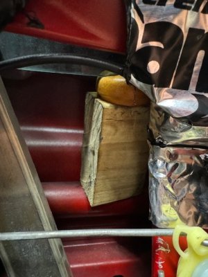
Regulator removal is detailed pretty well in pages 20-6,7 and Step 21 on page 20-10 of the Service Manual, except leave the glass in its up, closed position. Note that you are only removing the inner door cover and the regulator, not the window tracks. To secure the glass in the open position, there is a small ledge on the rear of the door where you can jam a small piece of 2 x 4 and other spacers you have available to prop it up. (I tried two kinds of tape using the instructions and the window fell both times but did not break.) It can be seen in the following picture inside the hole in the sound deadening mat placed by a prior owner (which has a gooey adhesive, so using this material is not recommended)
Step 2.
Pry back the regulator cover tabs with a large flat screwdriver, turn over and gently remove the cover. Also remove the O-ring and set aside to prevent damage.
Step 3.
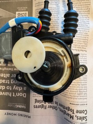
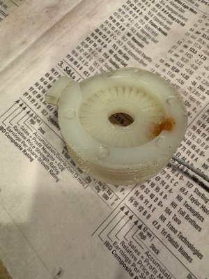
Retrieve the white plastic disc that will be stuck to the inside of the cover, place it over the spring and lift up the spring and its housing. Using the white plastic disc prevents direct contact with the spring and holds it in the housing securely to keep from unfurling. The toothed gear wheel and rubber spider drive can then be removed.
Step 4.
Before proceeding with Step 4, please see notes for Step 10 below, and consider pre-tensioning the springs at this time.
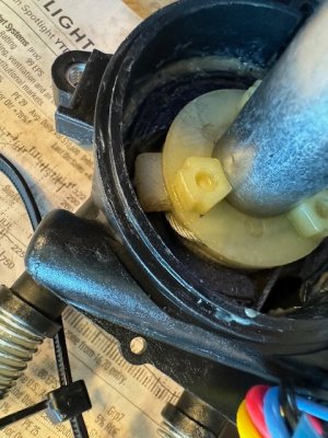
When manually lowering the regulator, press down on the white spindle with a 17mm socket to keep it intact. Observe how the wire rolls onto and off of the white core assembly. (This picture shows the wire protruding incorrectly, to be addressed below, this should not be seen at this point in the process, the picture is only meant to show placement of the 17mm socket for this step.)
Step 5.
After removing the two remaining core parts, I cannot see any need to totally “Remove both cables from the motor gear case.” Instead, it seems all work can be completed by just keeping slight tension on the cables inside the housing when needed to keep them from tangling.
Step 6.
The roller kit had a good fit and the roller tab between the washer and roller melds well on the regulator slot, install it with the center wire retaining tab pointed downwards. This is also the time to install the new track guides. The white plastic guide on top of the track is removed by lifting its tab on the back of the track and sliding it up. This allows the runner assembly to slide up off the track and allows the track guides to be removed (squeeze them to the center with pliers and remove) and the new ones to be installed (use pliers to gently squeeze them in place). Greasing the regulator track is important, as is cleaning and greasing the tracks remaining in the door. I used Gumout Carburetor Cleaner and patches of paper towel to clean all three tracks. The tracks in the door can be cleaned and greased in place with patience and stretching your arms through the access holes, including removing the speaker for another access hole. My lubricant was a 50/50 mixture of Honda Urea Grease and Quicksilver 802859Q1 2-4-C Marine Grease with Teflon, both available from Amazon. The urea grease alone seemed too thick and prone to hardening, but this is a personal preference.
Steps 7, 8, 9.
My axles did not have significant wear.
Step 10.
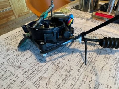
Before proceeding I recommend pre-tensioning the springs. (I even recommend doing this before starting Step 4 because the springs will already be tensioned and make tensioning easier.) The following crucial steps will be much easier, especially if you are working without an assistant. Pull both of the black rubber bellows up a few inches to expose the springs. Wrap a small tie wrap around each of the cable housings about ½” from their ends, capturing a larger tie wrap and cinch the small tie wrap. The larger tie wrap then goes around the regulator motor housing bolt, the ones loosened when the regulator was removed from the door. Tension the spring down carefully, making sure the cable housing and the spring and its white guide remain straight, then take the slack out of the larger tie wrap to secure everything in place. Make sure the small tie wrap does not slide down on the cable outer housing and pinch the cable. Both springs will compress fully. This is more simply shown in the following picture:
This is a good time to grease the bare shaft.
Then proceed with instructions to wind cable onto lower core part.
11. This step is easier with pre-compressed springs, but assure that the lower core cable wrapping remains taunt to keep cable in its grooves. A small C Clamp as pictured in the original instructions can be used, or just hold with finger and proceed to Step 12 if the springs are pre-tensioned.
12. This is the step needs to be done correctly and deserves extra attention. The object is to get the cable on the upper core part to lay into the upper groove of the lower core and pass into the recess of the lower core. The recess of the lower core can be seen at the 11:00 position, just to the right of the tab, in this picture:
Believe me, it is easy to get this wrong. The lower core has to be held taunt while the upper core wire is wound about 1/3 turn in its upper groove, passed into the slot shown in the picture above and also keeping the wire in the slot of the upper core. It’s not impossible, but it may take a few attempts. Once you have the wire in place, then hold the lower core taunt (clockwise for driver’s side, counterclockwise for passenger) and turn the upper core counterclockwise (counterclockwise for passenger) to tighten the wires. You will hear clicks and the goal is to get it as hand tight as possible. A screwdriver can be used to lever the upper core around, but with too much force it is possible to get the wires so tight that they bind, so the goal is a strong hand tight.
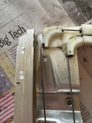
13. Use a light pressure on a 17mm socket placed over the core parts and manually raise the runner to the top. Observe the wires as they wind on and off the spindle to make sure they are not binding. Make sure the runner goes fully up and down without problem. It is best to make the runner go up and down a few times to observe for any problems. A couple of things to correct if observed include the wire coming out of its track on the upper white plastic piece
Or if you see the wire protruding from the spindle

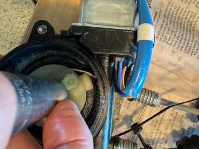
Or if the wire seems to be riding above the black housing and binding on the white plastic tab
Install the spider drive and toothed gear wheel, pushing it down fully in place, then the spring and housing can be installed and tension applied. The driver’s side, which is pictured in the directions will get pretension with 1½ turns clockwise and the passenger side will tension counterclockwise. The spring fits into the slot on the shaft, but may need to be bent to stay there when pretensioning. I had to bend mine to get it to stay, which is tricky and may take several attempts and may require bending a full circle of the spring to maintain placement in the slot. This would have been easier if Honda had used some sort of retainer. Afterwards, I wondered if putting a small scrap of metal in the shaft slot would have helped retain the spring tab in place.
Replace the white disc, O-ring and cover, bending the cover tabs back into place with channel-lock pliers spanned across both of them.
TESTING
I strongly recommend testing the operation of the assembled regulator by plugging it back into the door connector, then plugging in the switch. Holding the regulator and door panel while operating the regular with the door switch can be a handful, but it can be done to observe the operation and correct any problems. Take time and operate the regulator a few times listening and watching for any problems. Also note that the driver’s switch has to be connected for the passenger switch to work. I recommend carefully removing the cover once more and assuring the spring tab remained in place during this testing. Replace cover and install regulator.
Regulator Installation-Reverse of removal, the bottom of the regulator track is moved toward the front of the door and the track inserted, followed by the motor. Lower regulator about halfway until the bar that attaches to the window lines up with the hole just ahead of the large access hole, which leaves both bolt attachments visible and accessible. The chocks holding up the window installed in Step 1 can be removed and the window lowered manually to install the two bolts attaching the regulator to the window.
Test the window operation by cycling a few times before installing the door panel. The window should operate well with a fully charged battery and the engine off, but some have recommended running the engine for this test.
These are notes I compiled while installing the Hugo kits in my regulators, please add corrections if anything seems incorrect.
The Hugo Window Kit has been sold by various NSX Prime members, currently @whrdnsx is shipping them from Australia. The instructions are good if you already understand the process, but some clarification could benefit first-time users. Consider this an accompaniment rather than a replacement to the instructions. My notes follow them Step by Step.
It is also helpful to watch the YouTube videos, search for “NSX Window Regulator”, there are several.
Please note that the spring has a lot of tension and will need to be handled cautiously to keep it from jumping out of its housing, which could be hazardous.
Step 1.
Regulator removal is detailed pretty well in pages 20-6,7 and Step 21 on page 20-10 of the Service Manual, except leave the glass in its up, closed position. Note that you are only removing the inner door cover and the regulator, not the window tracks. To secure the glass in the open position, there is a small ledge on the rear of the door where you can jam a small piece of 2 x 4 and other spacers you have available to prop it up. (I tried two kinds of tape using the instructions and the window fell both times but did not break.) It can be seen in the following picture inside the hole in the sound deadening mat placed by a prior owner (which has a gooey adhesive, so using this material is not recommended)

Step 2.
Pry back the regulator cover tabs with a large flat screwdriver, turn over and gently remove the cover. Also remove the O-ring and set aside to prevent damage.
Step 3.
Retrieve the white plastic disc that will be stuck to the inside of the cover, place it over the spring and lift up the spring and its housing. Using the white plastic disc prevents direct contact with the spring and holds it in the housing securely to keep from unfurling. The toothed gear wheel and rubber spider drive can then be removed.

Step 4.
Before proceeding with Step 4, please see notes for Step 10 below, and consider pre-tensioning the springs at this time.
When manually lowering the regulator, press down on the white spindle with a 17mm socket to keep it intact. Observe how the wire rolls onto and off of the white core assembly. (This picture shows the wire protruding incorrectly, to be addressed below, this should not be seen at this point in the process, the picture is only meant to show placement of the 17mm socket for this step.)

Step 5.
After removing the two remaining core parts, I cannot see any need to totally “Remove both cables from the motor gear case.” Instead, it seems all work can be completed by just keeping slight tension on the cables inside the housing when needed to keep them from tangling.
Step 6.
The roller kit had a good fit and the roller tab between the washer and roller melds well on the regulator slot, install it with the center wire retaining tab pointed downwards. This is also the time to install the new track guides. The white plastic guide on top of the track is removed by lifting its tab on the back of the track and sliding it up. This allows the runner assembly to slide up off the track and allows the track guides to be removed (squeeze them to the center with pliers and remove) and the new ones to be installed (use pliers to gently squeeze them in place). Greasing the regulator track is important, as is cleaning and greasing the tracks remaining in the door. I used Gumout Carburetor Cleaner and patches of paper towel to clean all three tracks. The tracks in the door can be cleaned and greased in place with patience and stretching your arms through the access holes, including removing the speaker for another access hole. My lubricant was a 50/50 mixture of Honda Urea Grease and Quicksilver 802859Q1 2-4-C Marine Grease with Teflon, both available from Amazon. The urea grease alone seemed too thick and prone to hardening, but this is a personal preference.
Steps 7, 8, 9.
My axles did not have significant wear.
Step 10.
Before proceeding I recommend pre-tensioning the springs. (I even recommend doing this before starting Step 4 because the springs will already be tensioned and make tensioning easier.) The following crucial steps will be much easier, especially if you are working without an assistant. Pull both of the black rubber bellows up a few inches to expose the springs. Wrap a small tie wrap around each of the cable housings about ½” from their ends, capturing a larger tie wrap and cinch the small tie wrap. The larger tie wrap then goes around the regulator motor housing bolt, the ones loosened when the regulator was removed from the door. Tension the spring down carefully, making sure the cable housing and the spring and its white guide remain straight, then take the slack out of the larger tie wrap to secure everything in place. Make sure the small tie wrap does not slide down on the cable outer housing and pinch the cable. Both springs will compress fully. This is more simply shown in the following picture:

This is a good time to grease the bare shaft.
Then proceed with instructions to wind cable onto lower core part.
11. This step is easier with pre-compressed springs, but assure that the lower core cable wrapping remains taunt to keep cable in its grooves. A small C Clamp as pictured in the original instructions can be used, or just hold with finger and proceed to Step 12 if the springs are pre-tensioned.
12. This is the step needs to be done correctly and deserves extra attention. The object is to get the cable on the upper core part to lay into the upper groove of the lower core and pass into the recess of the lower core. The recess of the lower core can be seen at the 11:00 position, just to the right of the tab, in this picture:

Believe me, it is easy to get this wrong. The lower core has to be held taunt while the upper core wire is wound about 1/3 turn in its upper groove, passed into the slot shown in the picture above and also keeping the wire in the slot of the upper core. It’s not impossible, but it may take a few attempts. Once you have the wire in place, then hold the lower core taunt (clockwise for driver’s side, counterclockwise for passenger) and turn the upper core counterclockwise (counterclockwise for passenger) to tighten the wires. You will hear clicks and the goal is to get it as hand tight as possible. A screwdriver can be used to lever the upper core around, but with too much force it is possible to get the wires so tight that they bind, so the goal is a strong hand tight.
13. Use a light pressure on a 17mm socket placed over the core parts and manually raise the runner to the top. Observe the wires as they wind on and off the spindle to make sure they are not binding. Make sure the runner goes fully up and down without problem. It is best to make the runner go up and down a few times to observe for any problems. A couple of things to correct if observed include the wire coming out of its track on the upper white plastic piece

Or if you see the wire protruding from the spindle

Or if the wire seems to be riding above the black housing and binding on the white plastic tab

Install the spider drive and toothed gear wheel, pushing it down fully in place, then the spring and housing can be installed and tension applied. The driver’s side, which is pictured in the directions will get pretension with 1½ turns clockwise and the passenger side will tension counterclockwise. The spring fits into the slot on the shaft, but may need to be bent to stay there when pretensioning. I had to bend mine to get it to stay, which is tricky and may take several attempts and may require bending a full circle of the spring to maintain placement in the slot. This would have been easier if Honda had used some sort of retainer. Afterwards, I wondered if putting a small scrap of metal in the shaft slot would have helped retain the spring tab in place.
Replace the white disc, O-ring and cover, bending the cover tabs back into place with channel-lock pliers spanned across both of them.
TESTING
I strongly recommend testing the operation of the assembled regulator by plugging it back into the door connector, then plugging in the switch. Holding the regulator and door panel while operating the regular with the door switch can be a handful, but it can be done to observe the operation and correct any problems. Take time and operate the regulator a few times listening and watching for any problems. Also note that the driver’s switch has to be connected for the passenger switch to work. I recommend carefully removing the cover once more and assuring the spring tab remained in place during this testing. Replace cover and install regulator.
Regulator Installation-Reverse of removal, the bottom of the regulator track is moved toward the front of the door and the track inserted, followed by the motor. Lower regulator about halfway until the bar that attaches to the window lines up with the hole just ahead of the large access hole, which leaves both bolt attachments visible and accessible. The chocks holding up the window installed in Step 1 can be removed and the window lowered manually to install the two bolts attaching the regulator to the window.
Test the window operation by cycling a few times before installing the door panel. The window should operate well with a fully charged battery and the engine off, but some have recommended running the engine for this test.


