How to installation ABS Conversion?

Joined
25 September 2006
Messages
151
I just get ABS conversion harness NA1 => NA2.
but I cannot install It.

-Could you please tell me that how can I plug ABS Conversion Harness to ABS modulator plug?

I already slided plus but cannot put it in ABS modulator plug.(like it still stuck)
20112007.jpg


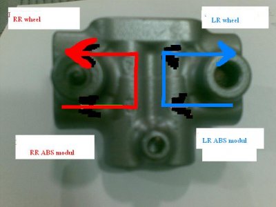
-I have another question about install Valve Assy Proportioning.

Could you tell me which direction is correct?
1
21112007001.jpg


or 2
21112007.jpg


Thank you so much.:smile:
Tum
 
I had the same problem with the connector. It turns out if you look inside the connector there's a white plastic pin retainer that needs to be pushed back into the connector. (It's sticking out a little that stops the connector pushing on to the ABS connector) This had me baffed for a little while too.

The Rear block will only mount one way on the bracket as it has a locating pin on one side. The brake lines will only fit up one way.

Hope this helps.
 
Last edited:
Thank you so much,whrdnsx
I can pluged it already,after 3 day ago.
You help me so much.
Thank you again.
Tum
 
This is the white plastic pin retainer that needs to be pushed back into the connector.:smile:

201120073.jpg
 
Hi Mrsarit,

I would be very interested in your findings concerning the differences between the old and the new ABS system.
Would like to hear if the conversion is actually worth doing.
 
Actually,My ABS is have many problem when I brough my
so I never know about old ABS
but I will report for new ABS.
Tum
 
What should these wires be line with?
25112007001.jpg

Sorry for many question that because I don't have english install manual.
Thank you.
Tum
 
hi Tum --

Did you ever determine what no. 1 & 2 are for?

Cheers,
-- Chris

1 & 2 are for the ABS Diagnostic tool I believe. (Just tape them to the Loom)

3 is Ground

4 & 5(not shown in photo) is 12V & Ground to be fitted into your old ABS 2 pin Connector (Orange) You will have to remove the Connector from your old ABS Unit with a small electronic screwdriver to release the Pins.

Hope this Helps
 
Ya just gotta love the collective knowledge on this board....unbelievable..


:)
 
1 & 2 are for the ABS Diagnostic tool I believe. (Just tape them to the Loom)

3 is Ground

4 & 5(not shown in photo) is 12V & Ground to be fitted into your old ABS 2 pin Connector (Orange) You will have to remove the Connector from your old ABS Unit with a small electronic screwdriver to release the Pins.

Hope this Helps

Thanks for the note. I was also able to confirm following the pin out that they are for the diagnostic tool.

Cheers,
-- Chris
 
Hi
This for pin 4&5
a10.jpg

and I hear pin 1&2 is for Diagnostic,like whrdnsx say, but I don't know how to use it.
I already installed it.
I will report about installation and result soon.
 
ABS conv/ Larry or Chris please?

Early in this thread the attached pictures were posted showing the operational orientation of the prop valve. I'm doing my conv now and since i don't have anything to look at, I thought I'd just start by seeing what lines fit where (I can't believe I admitted that out loud). It looks to me like the two rear lines from the modulator come in the two bottom connections on the valve and come out the two top, both on the same sides, unlike the photo's posted earlier. Can you guys give me confirmation on that? And for my double check, at the firewall junction block, which line is which, RR and LR. Got 15 inches of snow the other day here in Ohio. It's surreal shoveling snow and then working on an NSX a few minutes later. Thanks!
 
Last edited:
Hi
This for pin 4&5
a10.jpg

The connector that you see here is the power for the pump. There is a 40 amp fuse on the other end of the (+) wire so don't hook it up to the wrong thing. If you connect it to the wrong thing you will know because of the smoke that will come out.

Brad
 
Re: ABS conv/ Larry or Chris please?

Early in this thread the attached pictures were posted showing the operational orientation of the prop valve. I'm doing my conv now and since i don't have anything to look at, I thought I'd just start by seeing what lines fit where (I can't believe I admitted that out loud). It looks to me like the two rear lines from the modulator come in the two bottom connections on the valve and come out the two top, both on the same sides, unlike the photo's posted earlier. Can you guys give me confirmation on that? And for my double check, at the firewall junction block, which line is which, RR and LR. Got 15 inches of snow the other day here in Ohio. It's surreal shoveling snow and then working on an NSX a few minutes later. Thanks!

Tanto2

I think you are correct.
The pictures above is wrong.
Now,I connect like this picture...
 

Attachments

  • abs.jpg
    abs.jpg
    31.2 KB · Views: 171
The connector that you see here is the power for the pump. There is a 40 amp fuse on the other end of the (+) wire so don't hook it up to the wrong thing. If you connect it to the wrong thing you will know because of the smoke that will come out.

Brad


Thank Brad for your advice.

My NSX is 92 and old ABS modul have many problem.
so i change to newer ver.
Now,ABS is work and better than the old one (may be because of the old one is waste)
 
The connector that you see here is the power for the pump. There is a 40 amp fuse on the other end of the (+) wire so don't hook it up to the wrong thing. If you connect it to the wrong thing you will know because of the smoke that will come out.

Brad

That plug is for power coming from the harness on the car side. what I did was cut off the head of that plug and solder the two wires together with the two power wire on the New harness. Hope this helps
 
mrsarit, any updates? write-ups? :wink:

One question: What about the behaviour of the ABS LED in the dash. Does it light up while starting? What do you think was the hardest part?
Diagnostics: Is this usable in the NSX?
 
Maybe someone can help me out here.

Pic 1: Does this plug with the plastic looks ready to go or does it needs pushed back even more.

Pic 2: The 3rd plug from the left is the ABS module substitute which I've found under the glove box. But where goes the 2nd plug from the left goes to? It should be quite near to the ABS module but I didn't find it.
 
Last edited:
If it plug goes into the unit easily, it's OK. I didn't have to push mine much. BTW there are more posts for this thread as I don't see my posts on the harness intall. If you didn't know, you pull the orange lock collar up, push the plug in and then push the collar back down. Very slick. Seach for several more posts, and that layout above of the prop valve is WRONG!
 
Thanks for your help. This one http://www.nsxprime.com/forums/showthread.php?t=83018&page=2 also contains info about the conversion.

One question open. The white plug (not the one for the ABS control unit): where does it plug to?

nsxman2001 in the thread above wrote to this question:
The red plug goes into the new ABS Unit under the hood and white plugs you circled blue plugs into the orange plugs that your abs ECU is currently pluged into.. How that helped

So, does the ABS unit have two plugs? :confused: I only saw one of them.
 
Last edited:
So, does the ABS unit have two plugs? :confused: I only saw one of them.

My fault. I've found the ALB computer behind a big tube. It has two connectors. The first one I've 'found' was the one of the door lock.
 
Back
Top