Twin Turbo, inside engine compartment

Joined
13 September 2001
Messages
325
Location
Lake Mathews (Corona), Ca
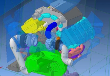
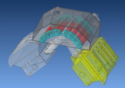
Here's a concept for twin turbos housed inside the engine bay. The design requires a fabricated intake with integrated Laminova core plenum. Core design shown is good for over 800 RWHP as are the turbos. Engine bay and glass are modeled in to check for interference.
 

Attachments

  • twin turbo 2.jpg
    twin turbo 2.jpg
    57.8 KB · Views: 386
  • twin turbo 3.jpg
    twin turbo 3.jpg
    53.6 KB · Views: 226
Last edited:
This was one configuration I had considered in the past since it would be so easy to do and a much more optimal configuration than anything else out there. However, the front bank turbo will require the exhaust to pass right where the front engine mount is... and there is not enough room even for small 1-3/4" piping. Hence my question on rigid engine mounts in this thread so I could re-engineer the front mount to provide the required clearance:
http://www.nsxprime.com/forum/showthread.php/156353-Anyone-Have-Rigid-Engine-Mounts?highlight=solid+engine+mounts

Right now, the way I am leaning for my custom twin turbo setup is to have my friend at Hogan make me custom IM's - one for each bank and each with their own TB. The front bank turbo will have the hot piping cross over to where the OEM fuel filter is. This may necessitate moving the engine bay brace where the fuel pump resistor mounts on depending on turbo frame size. I've already deleted the resistor, and have also plumbed my fuel supply and return lines where the coolant pipes go, so fuel vapor lock is not a concern. I don't want a full cage yet, but I will strengthen the weakened area with a roll bar tying back to the rear if/when I eventually do this.

The rear bank turbo will sit on top of the transmission. I can get BW EFR turbos for a good deal, so will probably go with those and monitor the turbine speed. That, combined with individual EGT's and O2 bank readings should provide enough information to tune everything well. No IC's - just 30/70 meth/water injection and a 5-gallon baffled tank in the trunk when I need it.

I'm curious on your thoughts and ideas how to work around the front engine mount being in the way. If this can be relocated with a different support, then I'd prefer the pictured configuration above too.

Dave
 
This looks good but i fear that there would be too much heat interference with the turbo being too close to the main coolant lines and tank.
 
Ditto. Plus, the sign of great aftermarket engineering is the ability to create what you want without the need to remove, remake or modify. You have a nifty idea here, but I question whether you gain as much as you sacrifice. Can you explain in no uncertain terms why this design is better than others out there and why it warrants making complex changes?
 
Like others are mentioning, I think there will be much more to consider than just placing these in those locations. There are a lot of items that reside in those spaces.

The SOS TT system places the turbos in the best location for a "in bay" TT setup IMO. Something placed where they have theirs with your IM would be interesting.
 
This was one configuration I had considered in the past since it would be so easy to do and a much more optimal configuration than anything else out there. However, the front bank turbo will require the exhaust to pass right where the front engine mount is... and there is not enough room even for small 1-3/4" piping. Hence my question on rigid engine mounts in this thread so I could re-engineer the front mount to provide the required clearance:
http://www.nsxprime.com/forum/showthread.php/156353-Anyone-Have-Rigid-Engine-Mounts?highlight=solid+engine+mounts

Right now, the way I am leaning for my custom twin turbo setup is to have my friend at Hogan make me custom IM's - one for each bank and each with their own TB. The front bank turbo will have the hot piping cross over to where the OEM fuel filter is. This may necessitate moving the engine bay brace where the fuel pump resistor mounts on depending on turbo frame size. I've already deleted the resistor, and have also plumbed my fuel supply and return lines where the coolant pipes go, so fuel vapor lock is not a concern. I don't want a full cage yet, but I will strengthen the weakened area with a roll bar tying back to the rear if/when I eventually do this.

The rear bank turbo will sit on top of the transmission. I can get BW EFR turbos for a good deal, so will probably go with those and monitor the turbine speed. That, combined with individual EGT's and O2 bank readings should provide enough information to tune everything well. No IC's - just 30/70 meth/water injection and a 5-gallon baffled tank in the trunk when I need it.

I'm curious on your thoughts and ideas how to work around the front engine mount being in the way. If this can be relocated with a different support, then I'd prefer the pictured configuration above too.

Dave


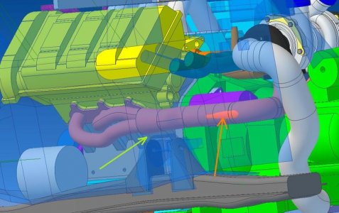
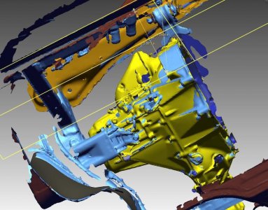
Although I don't have all the primary components modeled yet I will in the next few weeks. As of this moment I don't see any issue with routing either side of the exhaust system to/from the turbo (assuming a custom exhaust header). Shown are the actual scan data (polys) and the simplified CAD representations. The arrows show the critical clearences and where the current design passes through the firewall which requires some more rubbing on the design.

- - - Updated - - -

This looks good but i fear that there would be too much heat interference with the turbo being too close to the main coolant lines and tank.

Heat is always a concern but the amount of effective radiated energy compared to the amount/rate of heat flowing through coolant lines would be quite small. Some simple shielding or wrapping would be a solution if necessary.

- - - Updated - - -

Ditto. Plus, the sign of great aftermarket engineering is the ability to create what you want without the need to remove, remake or modify. You have a nifty idea here, but I question whether you gain as much as you sacrifice. Can you explain in no uncertain terms why this design is better than others out there and why it warrants making complex changes?

There are very few twin turbo systems "out there" so besides the advantage inherent with two small turbos over a single large one I'll limit my comparisons to the SOS system (which I think is pretty cool).

To mention a few off the TOMH . . . .
Better transient performance due to significantly shorter air paths.
Less pressure drop due to same.
A true “split” system isolating each bank (eliminates destructive interference within plenums inherent with even firing V6 engines)
More effective intercooling system.
Slightly better header design reducing destructive interference within exhaust.
More latitude for turbo sizing and styles
More efficient runner design (over stock manifold)
Easier access to turbos
Better oil drainage (more head pressure)
Much higher “cool factor”
Never been done before.

This is not something anyone other than folks wanting the most optimum performance as measured by gains compared to lag in a road racing type environment where derivability is a major factor in good lap times.

- - - Updated - - -

Like others are mentioning, I think there will be much more to consider than just placing these in those locations. There are a lot of items that reside in those spaces.

The SOS TT system places the turbos in the best location for a "in bay" TT setup IMO. Something placed where they have theirs with your IM would be interesting.

I'm trying to model in as many components as possible so I can assess just what would get in the way or need to be re-located, etc. It's not for the R&R car guy. I don't think the SOS system could take full advantage of the IM/intercooler capacity. It would be overkill. Any fewer cores would reduce the plenum size to an undesirable level (assuming the design was downsized to accomodate).
 

Attachments

  • twin turbo 5.jpg
    twin turbo 5.jpg
    64.1 KB · Views: 145
  • twin turbo 6.jpg
    twin turbo 6.jpg
    85.2 KB · Views: 143
Having the right tools to engineer this twin turbo is key, not just slapping together 2 turbos and adding pipes to make it work.


Bryan

My initial design as shown was just a proof of concept to verify the logistics and feasibility from a packaging/systems standpoint. If it looks feasible, then all the individual components will need to be optimized. Full scale Mockups will need to be made and fit checks done to further validate the models before any actual metal is cut. Form, fit and function will no doubt need to change and ultimately one or the other might put the kibosh on the whole deal. However, doing the detailed layout as shown lessens the odds that this will happen. For example, I’ll be modeling the IM/intercooler and running it through a CFD program before the design is finalized (I use Star-CD software). It might turn out to be inherently lousy design airflow wise. I’ll probably run a thermal analysis as well and it’ll tell me what I can expect efficiency wise, affects of different water flow rates, etc. A FEA analysis of the headers is probably in order as the stresses imposed by a turbo system are quite formidable. Obviously there are many more analysis that will need be performed. Finally, all the little support brackets and misc parts will need to be designed as you are 100% correct that simply “slapping together two turbos and adding pipes” is only a small part of the total engineering picture.

- - - Updated - - -

how about a supercharger for the bottom end and a turbo for the top end?

I’ve often considered that approach. IMO you'd need to figure out some way to "clutch" the blower so that it can be disengaged when the turbo kicks in. A powerful electro-magnet clutch might work. Also, you wouldn't want to route one system through the other so they'd need to be seperate systems with some kind of "diverter" valve for the airflow. However, creating the control system that would result in a seamless boost transition between blower and turbo would be quite an engineering challenge.
 
I really appreciate your expertise and knowledge. Instead of slapping things together, you obviously do a thorough job of thinking through things and considering all the implications. Thank you for sharing your ideas and work!

There is no perfect design of course when also considering time and cost. However, like you, I think there are creative new ways of approaching FI in our 1st-gen NSX's.

There are very few twin turbo systems "out there" so besides the advantage inherent with two small turbos over a single large one I'll limit my comparisons to the SOS system (which I think is pretty cool).

I like the SOS design too. It's a good effort and seems to work.However, the exhaust manifolds are the limitation. Honestly, they suck (and not in a good way). IMO, the primaries could have been made smaller, and the flange could have been arranged a bit more to allow a better path into the turbines for both the front and rear banks. I would like to instrument and log cylinder pressures on that design. I have a DAS already with a simple USB connection to a laptop, but need to purchase EGTs and cylinder pressure transducers to monitor what I'll eventually want. Here's a commercially-based cylinder pressure logger system already to go and some advantages to monitoring cylinder pressure:
http://www.tfxengine.com/software7.html

Therefore, I saw no way of having a good turbo collector design with this layout either over a year ago when I was removing my engine. I would hate to go to all the effort of doing this configuration and then compromise on the manifolds. These pictures were enough for me to conclude I could not force an efficient collector in this space:

attachment.php


attachment.php


IMO, the coolant lines, tank, and starter are OK. Signifcant space could be gained for a better collector design if the engine mount could be re-engineered by stiffening it up and lowering it down with an entirely new steel design.


I'm curious on your thoughts please about my other idea like I described earlier. Besides relocating fuel stuff, possibly the engine bay structural brace, possibly loosing the A/C compressor, and being pretty expensive with new IM's, it would also yield a potentially great layout.

Otherwise, my last semi-original idea would be to do an equal-length header and collector system like Autowave and a few others with sequential turbos right above the transmission. I have a friend doing this on his Audi S4 2.0 using the bypass valve design Audi has on their new 3.0V6 TDI sequential system.

Thanks,

Dave
 
What about the idea of having the exhaust ports within the cylinder V and mounting the turbo(s) on top of the engine?
I suppose this would be possible by exchanging the front and rear cylinder heads?
 
What about the idea of having the exhaust ports within the cylinder V and mounting the turbo(s) on top of the engine?
I suppose this would be possible by exchanging the front and rear cylinder heads?

Besides the coolant and oil interfaces between the block and heads being off, you'd also need to turn all of the pistons 180 degrees due to the different intake and exhaust valve diameters.

I've thought of this too. One of the few advantages to having a 90-degree V - all of that space. I'll bet this is what Honda is doing with the new NSX engine.

Dave
 
Back
Top