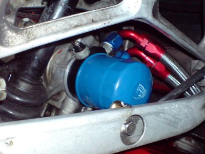
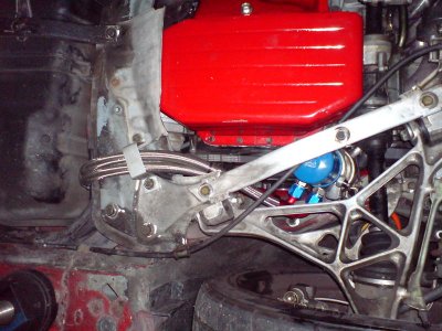
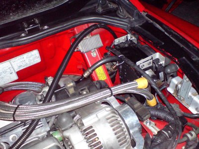
my better than nothing oil cooler
- Thread starter nsxhk
- Start date
Looks like it should function pretty well!
Thanks for posting this, Henry! Good initial fab work. When my car comes back, we'll be trying to mount this:

It's supposed to fit in the passenger side vent where the cooling fan is but needs some modication (actually a lot) in order to do so. The fan will mount on the back to pull air through and I wonder if the this arrangement (fan in back) would be better for your application as well. In addition, the hoses seem to fit over rear beam rather than under. I thought this may be better than under - to keep them away from potential ground clearance issues.
Is the rear beam bracket edges rolled or edged with rubber?
Again, nice work.
The fan will mount on the back to pull air through and I wonder if the this arrangement (fan in back) would be better for your application as well.
Won’t the fan have clearance issues with the fuel filter?
Are you planing on relocating the fuel filter ?
Then again your core is a little thinner then nsxhk’s.
What type of fan are you planing on fitting to this?
hi Shawn --
From memory, your Ron Davis radiator has built in oil cooling capability. These parts as shown would also alter how we are doing your Accusump. Please give me a ring when you get a chance.
Cheers,
-- Chris
From memory, your Ron Davis radiator has built in oil cooling capability. These parts as shown would also alter how we are doing your Accusump. Please give me a ring when you get a chance.
Cheers,
-- Chris
Thanks for posting this, Henry! Good initial fab work. When my car comes back, we'll be trying to mount this:

It's supposed to fit in the passenger side vent where the cooling fan is but needs some modication (actually a lot) in order to do so. The fan will mount on the back to pull air through and I wonder if the this arrangement (fan in back) would be better for your application as well. In addition, the hoses seem to fit over rear beam rather than under. I thought this may be better than under - to keep them away from potential ground clearance issues.
Is the rear beam bracket edges rolled or edged with rubber?
Again, nice work.
I don't want to hijack Henry's thread but to answer your questions:
Not really, b/c the the stock cooling fan will actually be moved farther away from the fuel filter. The entire unit will fit in the vent/fender area w/ the cooling fan attaching to the oil cooler. That's the plan anyway - there's some fab work that will be involved to make the entire unit a tad smaller and sealed up.
Not yet. But if there would be any clearance issues, it could be an option.
Was planning on the stock fan since it's a "pull" unit but there are several oil cooler manufacturers with integrated higher speed fans. I'm fairly certain I'll be going to a smaller, in overall size, oil cooler so...we'll see.
The set up pictured is by HKS and is supposedly a drop in installation.
Won’t the fan have clearance issues with the fuel filter?
Not really, b/c the the stock cooling fan will actually be moved farther away from the fuel filter. The entire unit will fit in the vent/fender area w/ the cooling fan attaching to the oil cooler. That's the plan anyway - there's some fab work that will be involved to make the entire unit a tad smaller and sealed up.
Are you planing on relocating the fuel filter?
Not yet. But if there would be any clearance issues, it could be an option.
What type of fan are you planing on fitting to this?
Was planning on the stock fan since it's a "pull" unit but there are several oil cooler manufacturers with integrated higher speed fans. I'm fairly certain I'll be going to a smaller, in overall size, oil cooler so...we'll see.
The set up pictured is by HKS and is supposedly a drop in installation.
This is what I got so far. It's still in the testing phase. So far no leaks :tongue:
hi Henry --
Looks nice. I'd recommend protecting the lines going against the front beam. adel clamps and some plastic or rubber bushing should work out nice. Do you have a fan on the cooler? I'd suggest this if you do not as the side vents do not have much air flow to reach up into the engine bay with out some ducting.
cheers,
-- Chris
You may want to consider adding a oil thermostat in line to the cooler, to direct the oil away from the cooler until it reaches temp. ( usually they are pre set to open at 180 deg.) Without a therm. many cars will run with too cool oil unless being thrashed on the track, and ultimately do more engine damage than just leaving it stock. Most racing supply places, like Pegasus, etc. carry them all set to connect with AN lines for under $75.
Thnx for all the tips guys :smile:
This is a Setrab oil cooler with fan pack which I got a few years ago from BakerPrecision. The fan is not visible in the picture but is actually inside the fender. I installed an on/off switch at the center console to control the fan manually. I thought about the thermostat control module but it's not really useful in my case. When I drive on track, I usually just leave the fan running all the time which works quite well. When I drive on the street, I just leave the fan off. I try to stay as simple as possible and away from automatic sensors cause they do malfunction from time to time, usually at those critical moments.
I'll rework the oil lines once I'm satisfied with its performance.
Henry.
This evening I finally finished plumbing together my revised oil system. I was originally going to submit this as an article for NSX Driver, but this seems to be the proper place to share.
I started off building my "better than nothing oil cooler system" by doing my best to ensure my oil stops getting cooked by my front header. Retaining the basic wet sump design, my oil is stored in the pan as opposed to the more ideal external container as would be in a dry sump system. An unfortunate design choice, our stock engine orientation has the front header running an inch under our oil pan which is contoured to allow for it. Our free-flowing exhaust systems get extremely hot on the track. My theory is that as the vehicle is constantly in VTEC, the low fluid volume sitting in the pan allows for a much more rapid sustained rate of heat transfer. Rather like boiling water, the less fluid volume v the lower the time to boil t. The hotter the oil the less effective it can become. Last season I had negligible airflow with my under trays in place, something the OE engineers could not have accounted for, heavily compounding this effect IMO.
I installed a Cool-It thermal blanket from Thermo-tec using clamps between the header and the pan. It's spec'd good for a 150 degree surface drop so long as you mount it loose, so as to leave a small pocket of air just above the manifold. The fit was perfect. Total cost, $16. The headers have an HPC ceramic coating.

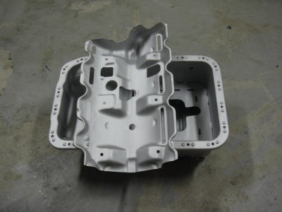
I further worked with a track pal (TitaniumDave) this season on oiling solutions out of necessity via revised car setup. I had my pan modified with a standard baffle, and tapped to my requirements with the necessary AN fittings, along with an extra AN-8 for a temp probe. I further had it coated internally with Teflon and a highly reflective exterior finish. We explored using hinges, but both agreed the standard baffle will be adequate for my specific application and direction. Once I get the final R&D and parts situated my final engine position this year will be slightly lower than stock, putting the pan as the lowest point in the vehicle. Again given negligible airflow from my engine under-pan, whereas before I had a NACA duct just fore it's position to keep air flowing around it, now I can tuck it just even with the tray moving more CFM while disrupting the air stream less in such a critical area.

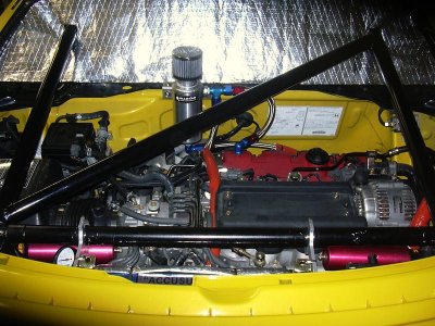
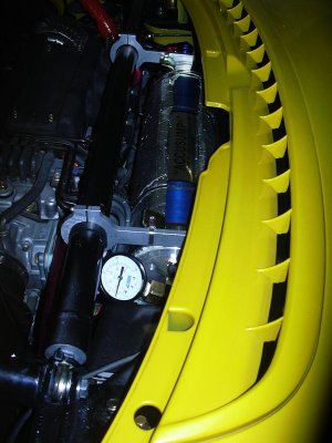
Next I mounted a 3 quart Accusump with EPC valve- expanding capacity, allowing for pre-lubrication, and ensuring pressure under high g loads. After some helpful back and forth calls to the staff at Canton, I finally opted for a unique mounting position just fore the rear hatch vent by minorly modifying my chassis allowing for adequate positioning. This shortened the oil line significantly, and allowed me to get the pressure sensor closer to the block. I was only able to do this as my rear hatch will mount entirely differently than stock and have few qualms about drilling out welds. I used Joe's mounts and Canton's clamps to secure the canister to the chassis and roll cage. I plumbed it into the stock oil cooler using a custom fitting Dave machines, an AN-12 line, Aeroquip fire sleeve, and an Adel clamp. Note the re-worked gauge position, for clearer visibility on keeping tabs on that pre-charge.
To help keep the sensitive piston and seals within allowable operating temps inside our engine bay, I made a custom carbon composite heat shield that is nearly thermally inert with a layer of mylar positioned out of view below it, and wrapped the accumulator with aluminized heat shielding. I plan to modify the stock rear garnish slightly, and my un-tested theory is that while it was designed more to let air escape the engine bay parked, in motion as small volumes of air enters the rear hatch vent, it will actually circulate over the top of the accumulator before the pressure differential pulls it back over the rear valve cover and out the back over the topside of the diffuser.

I then mounted a well designed catch tank. This specific one had a few nice features and meets tech. I had each valve cover tapped for AN-8 fittings, and ran AN-8 lines to the tank. A more unique feature, we further ran a return line back to the oil pan from the catch tank. This has several tangible benefits, aside from maintenance, such as if you subscribe to Rob's contention on crankcase pressurization.

I am now currently in the process of looking into re-locating the oil filter and designing a new cooling system which will also indirectly help, and I may well add further dedicated oil cooling capacity (air or water cooled with a regulator) once I get some on-track measurements this year on a data logger and get better field data on my oil conditioning needs. As a side note, I highly recommend using good hardware and AN- fittings as many kits just include rubber hoses or restrict mounting.
Total cost for the band aids was around $1200+- and a few days DIY, a real no-brainer given the high cost of our engines or for a dry sump quote. Many of the new European Exige's, notorious for blowing engines, now come stock with an accusump. It definitely affords me a lot of piece of mind having already lost one miata and one civic engine cornering. Many thanks to Dave, Rob, Canton, AR, HRP World, and friends for assisting and supplying parts for this minor yet well over-due project.
I started off building my "better than nothing oil cooler system" by doing my best to ensure my oil stops getting cooked by my front header. Retaining the basic wet sump design, my oil is stored in the pan as opposed to the more ideal external container as would be in a dry sump system. An unfortunate design choice, our stock engine orientation has the front header running an inch under our oil pan which is contoured to allow for it. Our free-flowing exhaust systems get extremely hot on the track. My theory is that as the vehicle is constantly in VTEC, the low fluid volume sitting in the pan allows for a much more rapid sustained rate of heat transfer. Rather like boiling water, the less fluid volume v the lower the time to boil t. The hotter the oil the less effective it can become. Last season I had negligible airflow with my under trays in place, something the OE engineers could not have accounted for, heavily compounding this effect IMO.
I installed a Cool-It thermal blanket from Thermo-tec using clamps between the header and the pan. It's spec'd good for a 150 degree surface drop so long as you mount it loose, so as to leave a small pocket of air just above the manifold. The fit was perfect. Total cost, $16. The headers have an HPC ceramic coating.
I further worked with a track pal (TitaniumDave) this season on oiling solutions out of necessity via revised car setup. I had my pan modified with a standard baffle, and tapped to my requirements with the necessary AN fittings, along with an extra AN-8 for a temp probe. I further had it coated internally with Teflon and a highly reflective exterior finish. We explored using hinges, but both agreed the standard baffle will be adequate for my specific application and direction. Once I get the final R&D and parts situated my final engine position this year will be slightly lower than stock, putting the pan as the lowest point in the vehicle. Again given negligible airflow from my engine under-pan, whereas before I had a NACA duct just fore it's position to keep air flowing around it, now I can tuck it just even with the tray moving more CFM while disrupting the air stream less in such a critical area.
Next I mounted a 3 quart Accusump with EPC valve- expanding capacity, allowing for pre-lubrication, and ensuring pressure under high g loads. After some helpful back and forth calls to the staff at Canton, I finally opted for a unique mounting position just fore the rear hatch vent by minorly modifying my chassis allowing for adequate positioning. This shortened the oil line significantly, and allowed me to get the pressure sensor closer to the block. I was only able to do this as my rear hatch will mount entirely differently than stock and have few qualms about drilling out welds. I used Joe's mounts and Canton's clamps to secure the canister to the chassis and roll cage. I plumbed it into the stock oil cooler using a custom fitting Dave machines, an AN-12 line, Aeroquip fire sleeve, and an Adel clamp. Note the re-worked gauge position, for clearer visibility on keeping tabs on that pre-charge.
To help keep the sensitive piston and seals within allowable operating temps inside our engine bay, I made a custom carbon composite heat shield that is nearly thermally inert with a layer of mylar positioned out of view below it, and wrapped the accumulator with aluminized heat shielding. I plan to modify the stock rear garnish slightly, and my un-tested theory is that while it was designed more to let air escape the engine bay parked, in motion as small volumes of air enters the rear hatch vent, it will actually circulate over the top of the accumulator before the pressure differential pulls it back over the rear valve cover and out the back over the topside of the diffuser.
I then mounted a well designed catch tank. This specific one had a few nice features and meets tech. I had each valve cover tapped for AN-8 fittings, and ran AN-8 lines to the tank. A more unique feature, we further ran a return line back to the oil pan from the catch tank. This has several tangible benefits, aside from maintenance, such as if you subscribe to Rob's contention on crankcase pressurization.
I am now currently in the process of looking into re-locating the oil filter and designing a new cooling system which will also indirectly help, and I may well add further dedicated oil cooling capacity (air or water cooled with a regulator) once I get some on-track measurements this year on a data logger and get better field data on my oil conditioning needs. As a side note, I highly recommend using good hardware and AN- fittings as many kits just include rubber hoses or restrict mounting.
Total cost for the band aids was around $1200+- and a few days DIY, a real no-brainer given the high cost of our engines or for a dry sump quote. Many of the new European Exige's, notorious for blowing engines, now come stock with an accusump. It definitely affords me a lot of piece of mind having already lost one miata and one civic engine cornering. Many thanks to Dave, Rob, Canton, AR, HRP World, and friends for assisting and supplying parts for this minor yet well over-due project.
Attachments
Last edited:
Hey Johnny Boy, excellent post but I'm seeing red Xs everywhere.
Hopefully that resolved the attachment issue.
Similar threads
- Replies
- 7
- Views
- 427
- Replies
- 0
- Views
- 51


