1. Very, very close to finding the static fuel multipliers
2. See response...
3. See response...
4. IAT fuel enrichment identified!
5. All ignition timing modifiers identified, some fuel modifiers (LTFTs/STFTs and IAT). The fuel program is very very long on this car and will require some significant time to research fully.
6. See response...
7. I have identified the status bit for open/closed loop and the program that selects on various variables (TPS, CTS, Engine Load, etc) what selects open/closed loop, as well as identifying the (separate) open and closed loop fuel maps.
8. Target idle tables (ROM) as well as current desired idle (RAM) have been identified and are obviously referenced to CTS. Also identified target idles for A/C on.
Dave,
Right now I've got #6 taken care of. I've identified the 3v (WOT - atmosphere) map sensor limit and I am able to raise it to 5v (10PSI on the stock MAP sensor) to prevent code 3 (MAP sensor electrical). I have also identified the routine that compares the map sensor against the barometric sensor to set code 5 (MAP sensor signal/vacuum). So, technically you would be able to run boost with these "caps" raised without going into limp mode and setting a CEL. BUT - the ECU doesn't have any programming to handle any voltages over 3v from the MAP sensor, which introduces this conundrum...
The trouble I'm having is with the routine that handles the map sensor calculations. The vast majority of the sensors within the ECU are 0-5v - obviously. The map sensor signal is the exception in that has it's own direct A/D conversion and is converted to an 8 bit value that represents 0-5volts (0=0volts, 255=5volts) this value is then stored in RAM. The map sensor routine then mathematically (subtracts a hard coded amount) converts this value so that it now represents 0-3volts (0=0volts, 255=3volts). So, the rest of the ECU program is calculated for the map sensor reading solely naturally aspirated 0-3v values. So, if that 0-3v value were to be modified to read 0-5v it seems it would throw the whole program out-of-whack.
My idea is to set up a status indicator that queries the MAP sensor and produces a boost/no boost flag. Then, modify the fuel and ignition map routines to include a boost table. The routine would reference the boost status flag and whenever the car is in boost it would use the 0-5v map signal to, modified "boost" MAP scalars and cause a switch to a "boost" table - effectively piggybacking the routine. This will enable extremely high resolution boost tuning. The problem I'm having with this is that the MAP sensor routine is run off of an interrupt and isn't easily accessible.
The interrupt tables and routine are hard-coded onto the MCU (processor), they aren't accessible through the external chip - YET. I am working on getting all of the ECU code - the portion of the code that's within the MCU and the code that is on the chip itself - running on the external chip. So far my results are promising but I really need the help of electrical engineer who has some experience with this old school stuff. I am able to get the program to run off chip briefly, but I believe I am having bus conflict or timing issues I simply don't have the knowledge to resolve. Attached is a schematic of the chip select signals and address lines. I need help rewiring IC404 to be active from 0000-BFFF instead of 8000-BFFF.

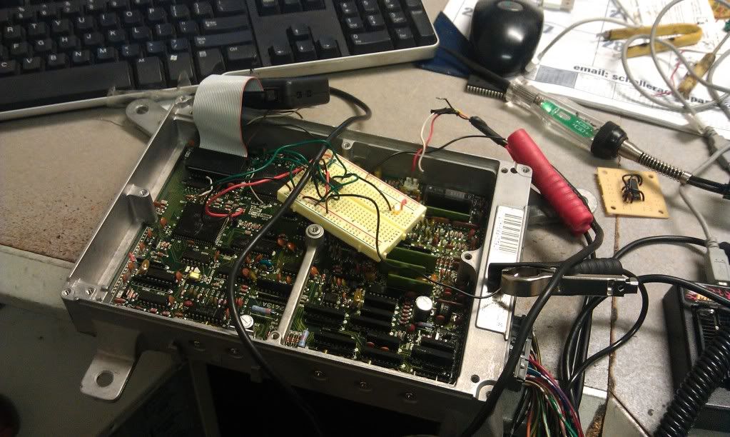
Heres a photo of my first attempt are rewiring for 0000-BFFF, as I said I was only partially successful.