factory keyless entry question

Joined
21 October 2003
Messages
401
Location
sunny so cal
I am currently installing a aftermarket alarm but I would like to integrate it to work with the OEM keyless entry.

does anyone have the diagram for the oem keyless entry?

btw, I've already searched and didnt find anything.
 
Joseph, does you new after-market alarm system not come with remote? It would make more sense I think to use this to both arm/disarm the alarm & also open the door-locks.
 
D'Ecosse said:
Joseph, does you new after-market alarm system not come with remote? It would make more sense I think to use this to both arm/disarm the alarm & also open the door-locks.

yes, the aftermarket alarm comes with the remote. What I intend to do is to also arm the factory alarm when when the button is pressed on the aftermarket alarm.

hope you understand
 
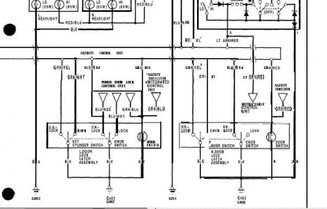
I do understand - this is possible & does not involve using the keyless entry module. All you have to do is tie the input of the door cylinder switch to the door lock knob switch. This will set the factory alarm when the door lock knob is set. If you use the one on the passenger door, the "lock" side of the lock knob switch is not even connected to anything. I don't think it would hurt anything to use the driver's door input either though. You can always use diode isolation or relay if you're concerned. The advantage of the driver's door is the wiring is already at the location of the security module/ door lock module behind the glove box.
I can draw up schematic modification for you if you need it.
http://www.nsxprime.com/FAQ/Reference/1991_svcman/1991servman.pdf - page 1293
 

Attachments

  • security.jpg
    security.jpg
    43.8 KB · Views: 735
I think I understand what you're telling me. But to be sure, please draw up a schematic modification.

thanks
 
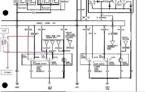
OK - Using a relay will keep the ccts completely isolated.

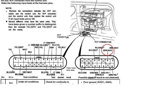
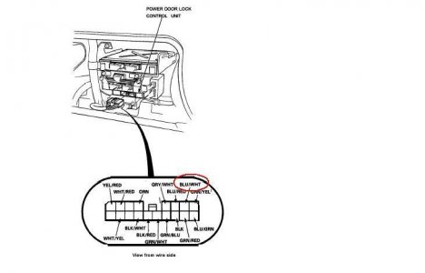
At the harness connector to the security module, identify the green/white wire & at the power lock module harness, the blue/white wire.
Use a 12V relay and connect the power side of the coil to 12V and the other end to a wire connected to the blue/white wire. Across the NO poles connect one wire to ground & another wire to the green/white wire. When the power lock button is down (locked position) the relay will energize & provide a ground to the key-lock switch,simulating a lock with the key & will arm the factory alarm. The disable is already provided in the std cct.

...
 

Attachments

  • security.jpg
    security.jpg
    63.9 KB · Views: 583
  • connector2.JPG
    connector2.JPG
    74.3 KB · Views: 625
  • connector1.JPG
    connector1.JPG
    29.8 KB · Views: 603
Ken - You are killing me. The breadth of your knowledge is amazing when it comes to these cars. So, here is goes:

I have an aftermarket alarm and keyless entry - I want to rip it out and throw it away. I want to replace it with the Acura keyless entry. How involved is that?????

PS - Let me know if you are able to go for a ride tomorrow.
Thanks, Michael
 
Cairo94507 said:
I have an aftermarket alarm and keyless entry - I want to rip it out and throw it away. I want to replace it with the Acura keyless entry.
Why would you want to do that??? Is there a problem with the unit or do you just want to go "stock"?
You will more likely have better protection with a modern alarm - if anything upgrade it to a new version if there's a problem with your current unit. The 2-ways are cool!
However if you want to remove it, shouldn't be too much trouble, assuming no wires have been cut - normally the alarm would be spliced into existing wiring, so just disconnecting the old alarm harness should be adequate. Then just follow the directions to install the factory keyless.
Still not 100% sure about tomorrow- looking less likely at this stage though.
 
OK - Using a relay will keep the ccts completely isolated.

At the harness connector to the security module, identify the green/white wire & at the power lock module harness, the blue/white wire.
Use a 12V relay and connect the power side of the coil to 12V and the other end to a wire connected to the blue/white wire. Across the NO poles connect one wire to ground & another wire to the green/white wire. When the power lock button is down (locked position) the relay will energize & provide a ground to the key-lock switch,simulating a lock with the key & will arm the factory alarm. The disable is already provided in the std cct.

...
A bit of a blast from the past, but if I follow your diagram and install this relay, when I lock my doors with the viper alarm system and I trigger the alarm, the headlights will roll up and the horn will blow? Like it already does when I lock it with the key and then trigger it?
 
Are you asking because you have tried and it isn't working or because you want to confirm that [MENTION=5957]D'Ecosse[/MENTION] 's method works? If the latter, I haven't done it; but, it may theoretically work. It is using the relay to mimic the existing arm function which comes from the key lock cylinder switch. The scheme requires the aftermarket keyless unit to lock the doors which operates the lock knob switch. The lock knob switch then operates the relay which creates a connection to ground on the Grn/Wht wire which should arm the SCU.

There are some iffy parts to the scheme. I believe the lock knob switch is continuously closed in the locked position which is going to hold the relay continually closed when locked. This adds a parasitic load of about 50 ma. The key cylinder switch is a momentary ground to arm the SCU when you lock the door. The relay imposes a continuous ground on that input as long as the car is locked. I don't know whether that presents a problem for the SCU. You may get a situation when you unlock the car - your keyless unit causes the lock knob switch to open which should de energize the relay; but, if the relay is slow to release you may get momentary conflicting inputs from the key switch inputs and lock knob inputs. I don't know whether that would present a problem for reliable operation of the SCU.

The OEM keyless unit uses a completely separate arm and disarm circuit for the SCU. On the 1997 and later pin-out for the 16 pin connector on the SCU you will find a brown wire on position A6 and a grey wire on position A15. The wires are shown in the pin-out diagram; but, they are not described in the service manual (you need the electrical trouble shooting manual for that) because the keyless unit was an accessory up to 2003. The brown wire is the arm input and the grey wire is the disarm input. On the later cars these two wires are brought out to connector C452 which is the interface plug to the accessory keyless unit. Unfortunately, my trouble shooting manual is not accessible so I can't tell you whether the inputs are momentary or continuous and whether they are ground or +12v. However, if I were to bet it would be that they are a momentary ground to arm or disarm. Using the existing arm and disarm inputs would be the most reliable way to retain operation of the existing security system.
 
As requested. Pre 2002 keyless unit external wiring diagram.
 
Last edited:
Back
Top